Question
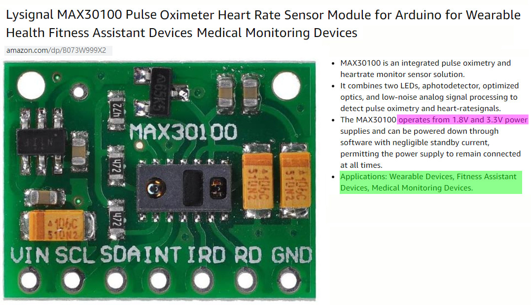
The OP has setup and successfully detected an I2C MAX30100 Pulse Oximeter and Heart-Rate Sensor module. But when trying to read the sensor, he encounters two problems:
(1) Gets the "Exception remote I/O error [error 121]",

(2) Gets only zero values for the red LED and IR Led outputs.
How to fix it?
Answer
Updates
Body is limited to 30000 characters; you entered 36021.
I am trying to insert some updates in the following penzu reading and experiment logs:
(1) MAX30102 Reading and Experiment Log V0.4 - 2020may04
(2) MAX30102 Reading and Experiment Log V0.6 - 2020may11
/ to continue, ...
Part A - Setting up and preliminary testing
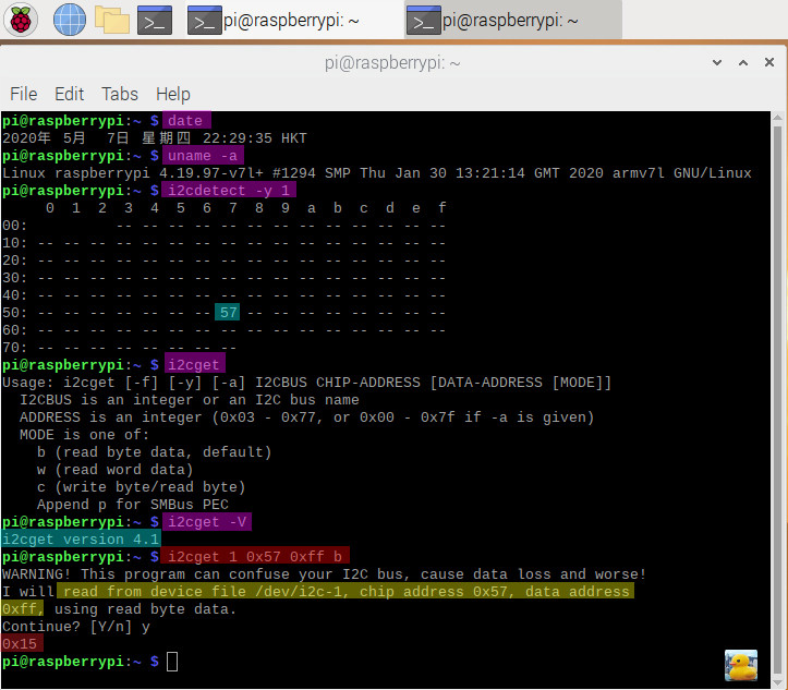
(1) Suggest to check I2C wiring and use "i2cdetect" and "i2cget" to find max30100 chip at I2C Bus #1, I2C device address 0x57, and Part ID 0x11 or 0x15 at max30100 register address 0xFF, as show below. (Note: MAX30100 Part ID is 0x11, MAX30102 is 0x15)
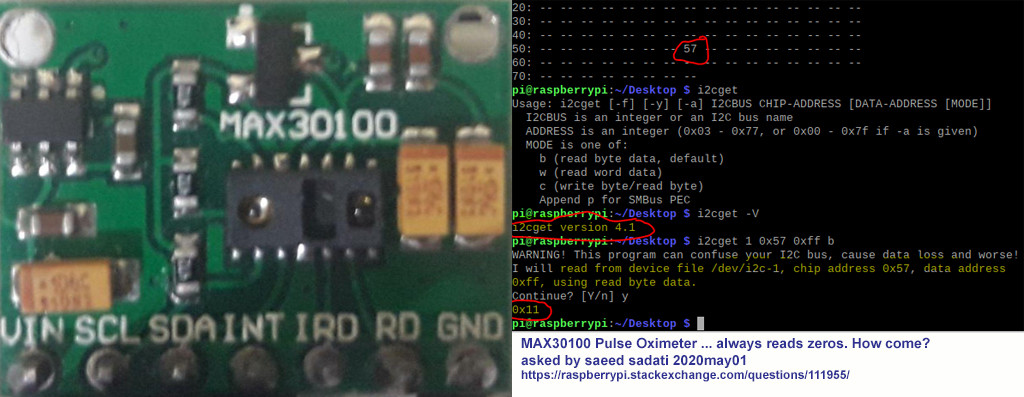
(2) The OP's Test Results
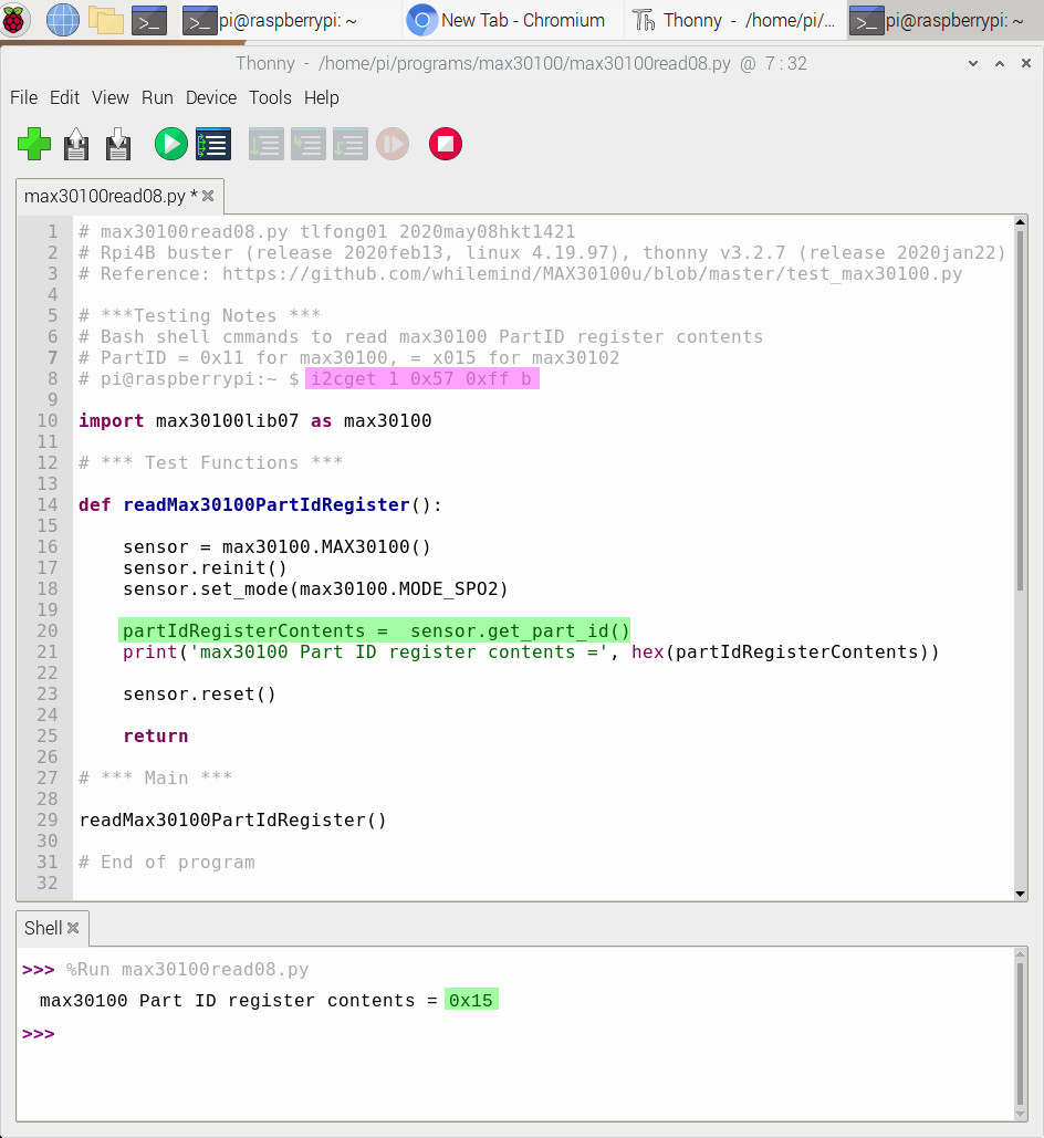
(3) Using max30100's library methods to read PartID register OK.
/ to continue, ...
Part B - Pulse Oximeter and Heart Rate Measurements
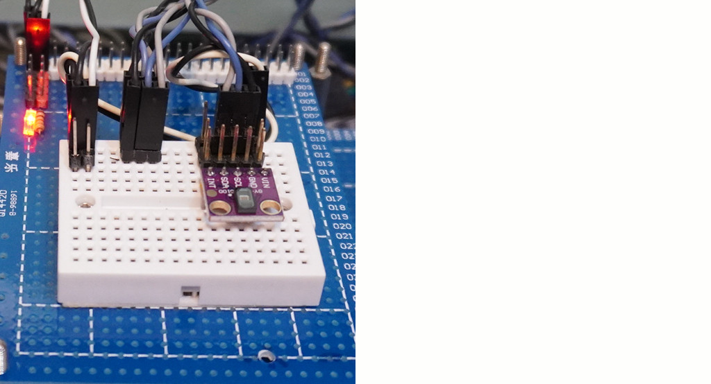
(1) Hardware Setup
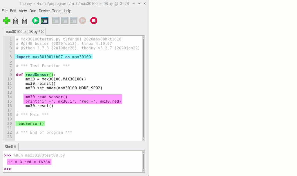
(2) The simplest read sensor program
(3) Minimal program to read registers and sensor
Sample Output
partID = 0x15
revID = 0x3
temperature = 14.9375
ir = 3 red = 1
ir = 3 red = 1
ir = 3 red = 1
ir = 3 red = 1
# max30100test12.py tlfong01 2020may08hkt1941
# Rpi4B buster (2020feb13), linux 4.19.97
# python 3.7.3 (2019dec20) thonny v3.2.7 (2020jan22)

import max30100lib07 as max30100

# *** Test Function ***

sensor1 = max30100.MAX30100()

def setupSensor(sensor):
    sensor.reinit()
    sensor.set_mode(max30100.MODE_SPO2)
    return

def resetSensor(sensor):
    sensor.reset()
    return

def readRegisters(sensor):
    # *** Read PartId ***
    partId =  sensor.get_part_id()
    print('partID      =', hex(partId))

     # *** Read Rev Id ***
    revId =  sensor.get_rev_id()
    print('revID       =', hex(revId))

    # *** Read Temperature ***
    temperature =  sensor.get_temperature()
    print('temperature =', temperature)

    return

def readSensor(sensor):
    totalCount = 4
    for count in range(totalCount):
        sensor.read_sensor()
        print('ir          =', sensor.ir, '          red           =', sensor.red)
    return

# *** Main ***

setupSensor(sensor1)
readRegisters(sensor1)
readSensor(sensor1)
resetSensor(sensor1)

# *** End of program ***

# *** Sample output  tlfong01  2020may08hkt2135 ***
'''
>>> %Run max30100test12.py
partID      = 0x15
revID       = 0x3
temperature = 14.9375
ir          = 3           red           = 1
ir          = 3           red           = 1
ir          = 3           red           = 1
ir          = 3           red           = 1
>>>
'''
# *** End of Sample output ***
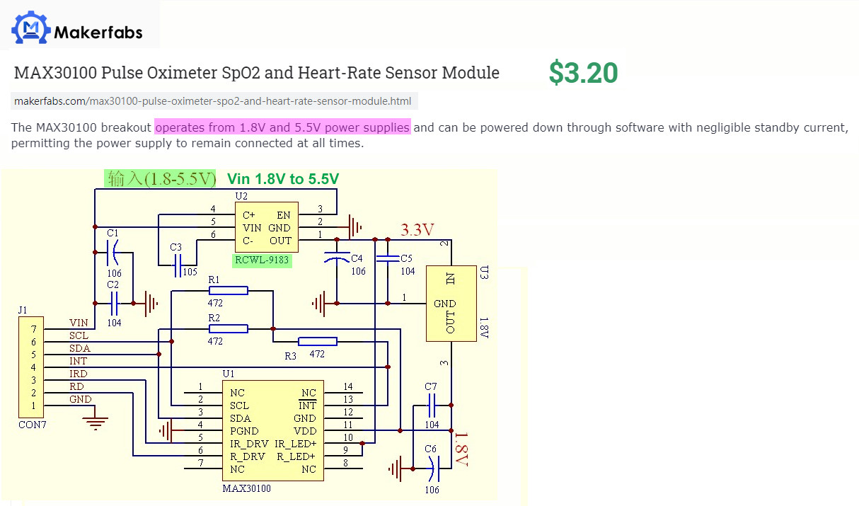
(4) What sort of power supply should be used for the MAX30102 Board?
When I first read the MAX30100 board schematic, I was confused about the 6 pin component marked in Chinese "Input 1.8V to 5.5V". I googled around and found users claiming different things, from the board is wrong, to how to removed the 4k7 pullup resistor external to the board and connect them to 2.8V or 3.3V. It is only after I figured out why there is a 6 pin voltage regulator then I realize what should I do, like (1) Should removed the 4k7s out and connect to 2.8V, or 3.3V, or even 5V, if I am stepping up Rpi I2C signals from 3V3 to 5V, ...
(5) Which python library should I use for MAX30102?
I have been using the whilemind library and found it very newbie friendly and easy to use and expand. However, I found it not too powerful and flexible. For example, mfitzp.py library, has interrupt and gpioZero features, seems to be more user friendly, and easier to use.
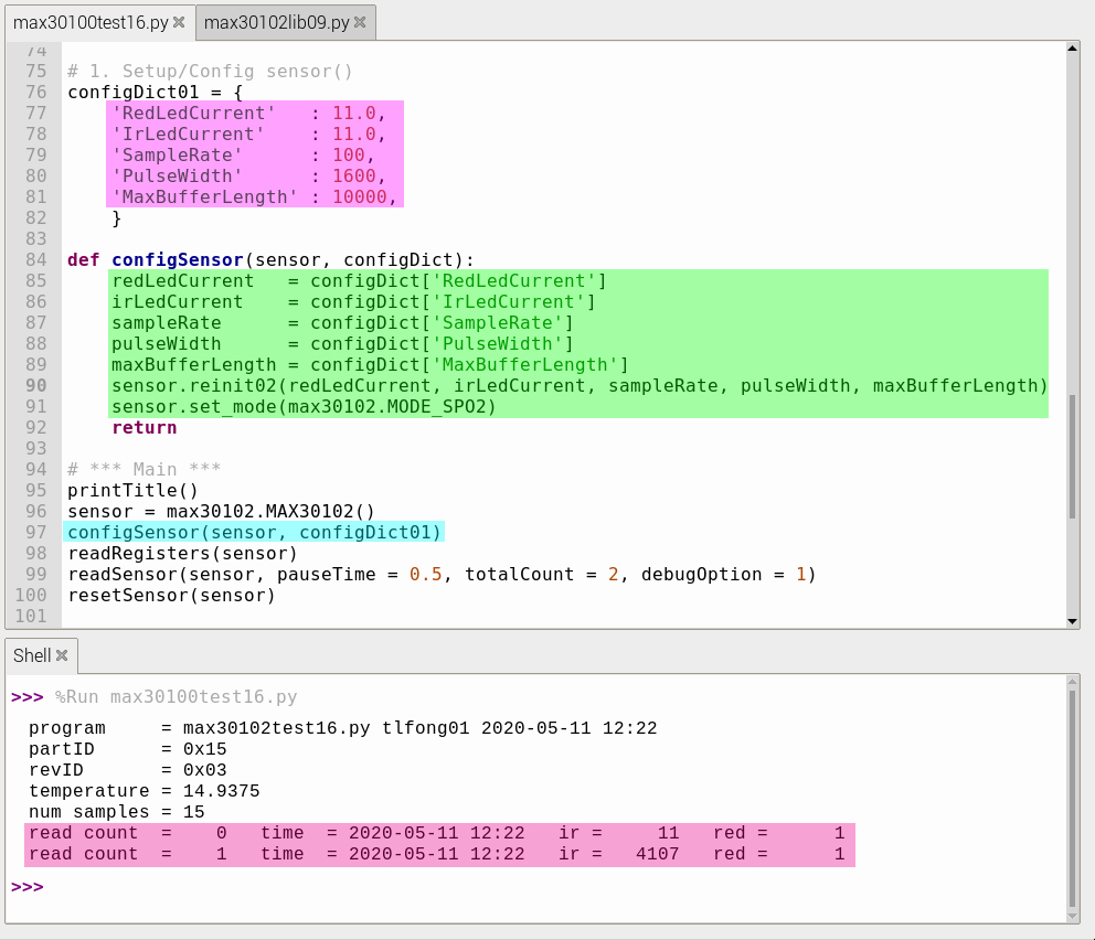
(6) Measurement performance of variable values of LED current, pulse width, sample rate etc.
/ to continue, ...
References
(1) MAX30100 Pulse Oximeter and Heart-Rate Sensor IC for Wearable Health Datasheet - Maxim
(2) MAX30102 High-Sensitivity Pulse Oximeter and Heart-Rate Sensor for Wearable Health - Maxim
(3) whilemind/MAX30100u max30100 Library
(4) whilemind/MAX30100u max30100 Class (max30100.py)
(5) whilemind/MAX30100u max30100 Test (test_max30100.py)
(6) mfitzp/max30100 max30100 Library
(7) kontakt/max30100 Library
(8) Amazon MAX30100 Pulse Oximeter Heart Rate Sensor Module - Lysignal
(9) AliEXpress GY-MAX30100 Pulse Oximeter Heart Rate Sensor Module - US$7
(10) TaoBao Risym GY-MAX30100 MAX30102 Pulse Oximeter Heart Rate Sensor Module - ¥35
(11) Amazon MAX30102 Pulse Oximeter Heart Rate Sensor Module
(12) Pulse Oximeter Instructable - MolecularD 2019sep
(13) max30100/102 pulse sensor discussion - ParticleCommunity
(11) TaoBao GY-MAX30100 MAX30102 Pulse Oximeter and Heart-Rate Sensor - ¥35
(12) Pulse Oximeter Instructable - MolecularD 2019sep
(13) Amazon max30102 Pulse Oximeter and Heart-Rate Sensor
(14) Particle.Community max30100 Forum Discussion
(15) Implementing pulse oximeter using MAX30100 Blog - Raivis Strogonovs 2017
(16) Max30100 Heart Rate Monitor Youtube Video - Maxim
(17) AD8232 ECG / Haeart Rate Sensor Rpi.StackExchange Forum Discusson
(18) Oxygen Saturation - Wikipedia
(19) Pull-up Resistors Tutorial - Electronics.Tutorials
(20) Application note AN10441 Level shifting techniques in I2C-bus design R0.1 2007jun18 - NXP
(21) I2C Bus Pullup Resistor Calculation, Application Report SLVA689, TI 2015feb
(22) Setting up multiple I2C buses using dtoverlay [Rpi4B] - rpi.stackexchange forum post 2019sep30
(23) What is Rpi4B I2C Maximum Speed?
(24) A Guide to Voltage Translation With TXS-Type Translators - TI
(25) MAX30100/02 Oximeter – How to fix wrong board - Valeriy Yatsenkov 2018aug22
(26) SC6206B LDO 65K5 (1V5 to 5V0, 250 mA) Datasheet - LCSC
(27) Max30100 pulse Oximeter Arduino Code, circuit, and Programming - Engr Fahad, Electronic Clinic 2020feb23
(28) How pulse oximeters work explained simply - Howeauipmentworks
(29) MAX30100 Pulse Oxmeter and Heart Rate Sensor (Arduino 5V input, use external 4k7 pullup to 5V, instead of 1V8)
(30) MAX30105 Particle and Pulse Oxmeter (Vin 5V, green LED won't work if Vin is 3V3)
(31) Bash V5.0 User Manual - 2019may
(32) Introducing Collections on Stack Overflow for Teams
(33) MAX30100 Pulse Oximeter SpO2 and Heart-Rate Sensor Module
(34) Pulse Oximeter Data Capture With Raspberry Pi - timbarnes 2015
(35) Using Collections for New Hire Onboarding - Stack Overflow for Teams - 2020apr30, YouTube 61 views
(36) MaximIntegratedRefDesTeam/RD117_ARDUINO (max30102.cpp) Maxim
(37) vrano714/max30102-tutorial-raspberrypi
(38) Arduino Pulse Oximeter Using MAX30100By vandyPulseOx
(39) Read a block of data from a specific register(fifo) using c/c++ and i2c in raspberry Pi
(40) How do I ask a good question? - StackOverflow
(41) Writing the prefect question - Jonskeet 2010aug29
(42) How to create a Minimal, Reproducible (Reprex, Mcve, Mwe) Example - StackOverflow
(43) How To Ask Questions The Smart Way - ES Raymond and Rick Moen, 2014
(44) Good Subjective, Bad Subjective Questions - Robert Cartaino, StackOver Blog 2010
(45) MAX30105 Particle Sensor Breakout - SparkFun $14
(46) MAX30105 Particle and Pulse Ox Sensor Hookup Guide - SprakFun
(47) SparkFun MAX30101 & MAX32664 Pulse Oximeter and Heart Rate Sensor US$40
(48) vrano714/max30102-tutorial-raspberrypi - Tutorial
(49) vrano714 max30102-tutorial-raspberrypi/max30102.py (162 lines) - Library
(50) vrano714 max30102-tutorial-raspberrypi Make Graph
(51) max30102 Arduino Heart Rate Monitor Using MAX30102 and Pulse Oximetry (python serial saving and FFT) - Joshua Hrisko, makersportol, 2019jun29
(52) Pulse Oximetry Lecture - Medical Electronics Lecture, Oxford University 2001
/ to continue, ...
Appendices
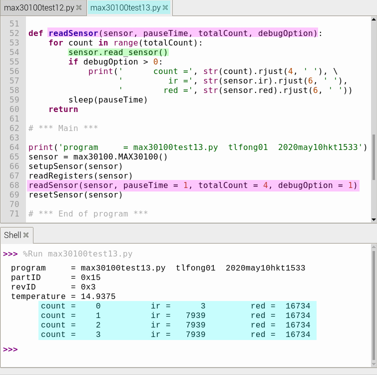
Appendix A - MAX30100 Test Program v13 - Repeat reading Sensor
# max30100test13.py tlfong01 2020may10hkt1502
# Rpi4B buster (r2020feb13), linux 4.19.97
# python 3.7.3 (r2019dec20) thonny v3.2.7 (r2020jan22)

# *** Import ***

from time import sleep
import max30100lib07 as max30100

#*** Setup / Configuration ***

# sensor1 = max30100.MAX30100()

# *** Test Functions ***

# Contents
# 1. Setup sensor()
# 2. Reset senor()
# 3. Read registeres()
# 4. Read sensor()
# 5. Repet read sensors()

# 1. Setup sensor()
def setupSensor(sensor):
    sensor.reinit()
    sensor.set_mode(max30100.MODE_SPO2)
    return

# 2. Reset senor()
def resetSensor(sensor):
    sensor.reset()
    return

# 3. Read registeres()
#    Read PartID, RevID, temperature
def readRegisters(sensor):
    # *** Read PartId ***
    partId =  sensor.get_part_id()
    print('partID      =', hex(partId))

     # *** Read Rev Id ***
    revId =  sensor.get_rev_id()
    print('revID       =', hex(revId))

    # *** Read Temperature ***
    temperature =  sensor.get_temperature()
    print('temperature =', temperature)

    return


def readSensor(sensor, pauseTime, totalCount, debugOption):
    for count in range(totalCount):
        sensor.read_sensor()
        if debugOption > 0:
            print('      count =', str(count).rjust(4, ' '), \
                  '         ir =', str(sensor.ir).rjust(6, ' '),
                  '        red =', str(sensor.red).rjust(6, ' '))
        sleep(pauseTime)
    return

# *** Main ***

print('program     = max30100test13.py  tlfong01  2020may10hkt1533')
sensor = max30100.MAX30100()
setupSensor(sensor)
readRegisters(sensor)
readSensor(sensor, pauseTime = 1, totalCount = 4, debugOption = 1)
resetSensor(sensor)

# *** End of program ***
/ to continue, ...
Figures
Fig 1 - MAX3010x System Diagram
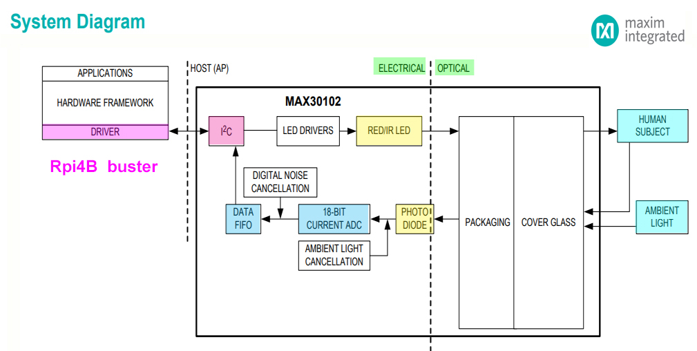
Fig 2 - MAX3010x Function Diagram
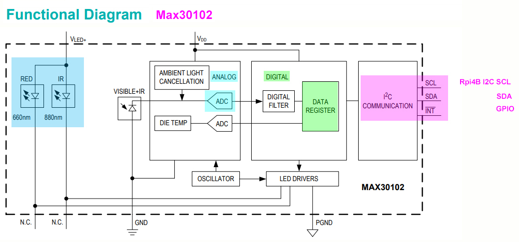
Fig 3 - MAX3010x Register Map Summary
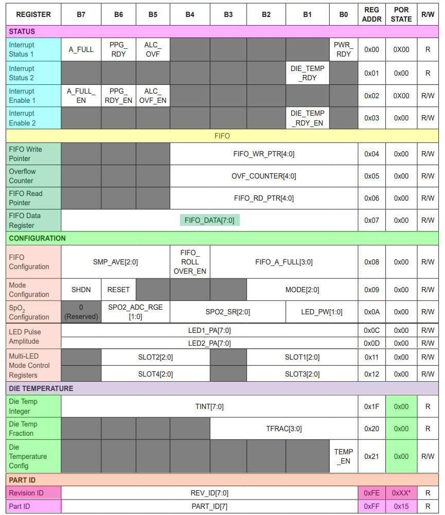
Fig 4 - GY-MAX30102 Module Schematic
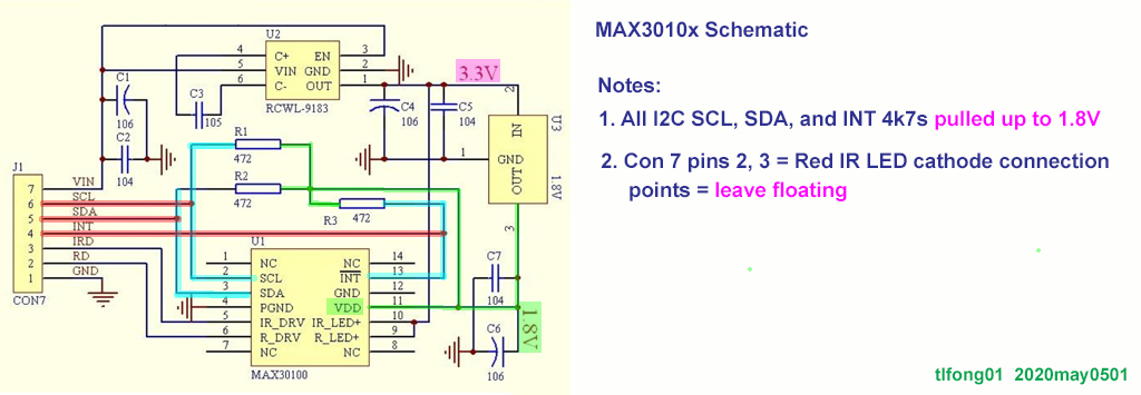
Fig 5 - GY-MAX00 ProductSheet
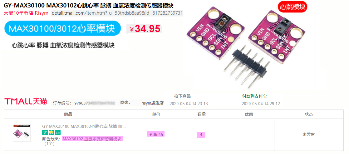
Fig 6 - GY-MAX30100 PCB Components Layout Diagram
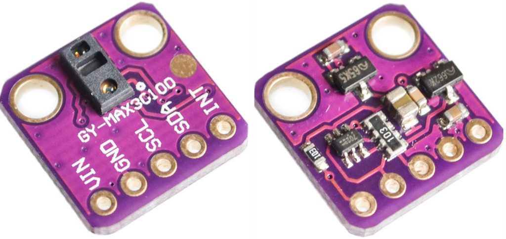
Fig 7 - Rpi4B to MAX30100 Module Wiring Diagram
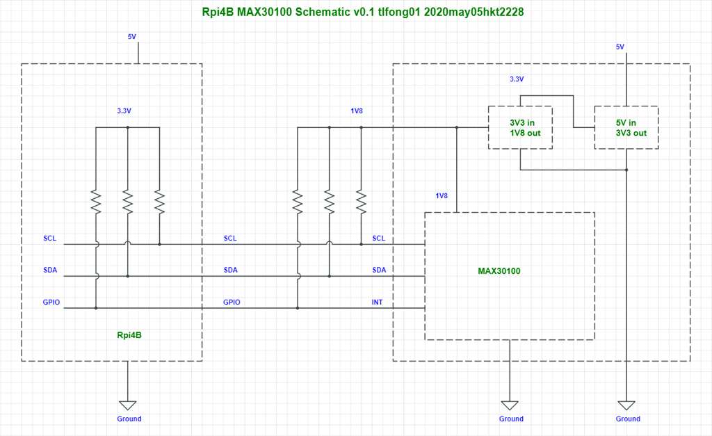
Fig 8 - MAX30102 PCB and Components Layout
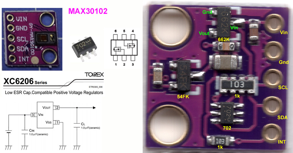
Fig 9 - MAX30100 Module Voltage Input Vin = 1.8V to 5.5V

Program Listings
(1) read_max30100.py tlfong01 2020may05hkt1936
# read_max30100.py tlfong01 2020may05hkt1936
# Rpi4B buster (release 2020feb13, linux 4.19.97), thonny v3.2.7 (release 2020jan22)
# Reference: https://github.com/whilemind/MAX30100u/blob/master/test_max30100.py

import max30100

# import max30100lib07 as max30100

# *** Test Functions ***

def readMax30100PartIdRegister():

    sensor = max30100.MAX30100()
    sensor.reinit()
    sensor.set_mode(max30100.MODE_SPO2)

    partIdRegisterContents =  sensor.get_part_id()

    # partIdRegisterContents = 'fakeFakeFake'

    print('max30100 Part ID register contents =', partIdRegisterContents)

    sensor.reset()

    return

# *** Main ***

readMax30100PartIdRegister()

# End of program
(2) Setting up multiple I2C buses
# fi2c62.py  tlfong01 2019aug28hkt1433

from time          import sleep
import             smbus
import             fprint53    as fprint
import             ftime53     as ftime

# I2c Bus Setup Notes
# pi@raspberrypi:~ $ date Wed 28 Aug 2019 03:26:24 PM HKT
# pi@raspberrypi:~ $ uname -a
# Linux raspberrypi 4.19.58-v7l+ #1245 SMP Fri Jul 12 17:31:45 BST 2019 armv7l GNU/Linux
# pi@raspberrypi:~ $ sudo nano /boot/config.txt
# dtoverlay=i2c1,pins_2_3  (board pins 3, 5)
# dtoverlay=i2c3,pins_4_5  (board pins 7, 29)
# dtoverlay=i2c4,pins_6_7  (board pins 31, 26)
# dtoverlay=i2c5,pins_12_13 (board pins 32, 33)
# dtoverlay=i2c6,pins_22_23 (board pins 15, 16)
# pi@raspberrypi:~ $ ls /dev/i2c*
# /dev/i2c-1  /dev/i2c-3  /dev/i2c-4  /dev/i2c-5  /dev/i2c-6

# ********************************************************************************
# ********************************************************************************

# *** I2c Bus Config ***

i2cBus1 = smbus.SMBus(1)
i2cBus3 = smbus.SMBus(3)
i2cBus4 = smbus.SMBus(4)
i2cBus5 = smbus.SMBus(5)

i2cBusDict = {'I2cBus1': i2cBus1,
              'I2cBus3': i2cBus3,
              'I2cBus4': i2cBus4,
              'I2cBus5': i2cBus5,
             }

# *** Pca9685 I2c Slave Device Congif ***

pca9685DevAddrDict = {
                'Dev0': 0x40,
                'Dev1': 0x41,
                'Dev2': 0x42,
                'Dev3': 0x43,
                'Dev4': 0x44,
                'Dev5': 0x45,
                'Dev6': 0x46,
                'Dev7': 0x47,
              }

pca9685RegAddrDict = { 'Mode1': 0x00,
                       'Mode2': 0x01,
                     }

pca9685DataByteDict = {
                       'Mode1Reset': 0x11,

    }

# ********************************************************************************
# ********************************************************************************

# *** Read Write Print Device/Register Functions ***

def writeDevTwoBytes(i2cBus, devAddr, writeByte1, writeByte2):
    i2cBus.write_byte_data(devAddr, writeByte1, writeByte2)
    return

def writeRegOneByte(i2cBus, devAddrDict, devName, regAddrDict, regName, writeByte):
    devAddr = devAddrDict[devName]
    regAddr = regAddrDict[regName]
    writeDevTwoBytes(i2cBus, devAddr, regAddr, writeByte)
    return

def readDevOneByte(i2cBus, devAddr, readByteAddr):
    readByte = i2cBus.read_byte_data(devAddr, readByteAddr)
    return readByte

def readRegOneByte(i2cBus, devAddrDict, devName, regAddrDict, regName):
    devAddr = devAddrDict[devName]
    regAddr = regAddrDict[regName]
    readByte = i2cBus.read_byte_data(devAddr, regAddr)
    return readByte

def printRegOneByte(i2cBus, devAddrDict, devName, regAddrDict, regName):
    readByte = readRegOneByte(i2cBusName, devAddrDict, devName, regAddrDict, regName)
    print(printTitle, hex(readByte))
    return

# *** Main Test Function ***

def testWriteReadPca9685Bus1Dev0RegMode1():
    fprint.printBeginExecFunction()

    i2cBusName = 'I2cBus1'
    devName    = 'Dev0'
    regName    = 'Mode1'

    #i2cBus      = fi2c.i2cBusDict[i2cBusName]
    i2cBus      = i2cBusDict[i2cBusName]
    devAddrDict = pca9685DevAddrDict
    regAddrDict = pca9685RegAddrDict

    writeByte = 0x77

    writeRegOneByte(i2cBus, devAddrDict, devName, regAddrDict, regName, writeByte)
    readByte = readRegOneByte(i2cBus, devAddrDict, devName, regAddrDict, regName)

    if readByte == writeByte:
        resultsString = 'Good'
    else:
        resultsString = 'Bad'

    devAddr = devAddrDict[devName]

    fprint.printTitleOneByteNum('PCA9685 I2C Address',             fprint.indentFormat640, devAddr)
    fprint.printTitleOneByteNum('PCA9685 MODE1 Register Written',  fprint.indentFormat640, writeByte)
    fprint.printTitleOneByteNum('PCA9685 MODE1 Register Read',     fprint.indentFormat640, readByte)
    fprint.printTitleString('Write/Read Results',                  fprint.indentFormat640, resultsString)

    fprint.printEndExecFunction()
    return

def testPingPca9685Bus1Dev0RegMode1():
    fprint.printBeginExecFunction()

    i2cBusName = 'I2cBus1'
    devName    = 'Dev0'
    regName    = 'Mode1'

    #i2cBus      = fi2c.i2cBusDict[i2cBusName]
    i2cBus      = i2cBusDict[i2cBusName]
    devAddrDict = pca9685DevAddrDict
    regAddrDict = pca9685RegAddrDict

    devAddr = devAddrDict[devName]

    readByte = readRegOneByte(i2cBus, devAddrDict, devName, regAddrDict, regName)

    compareByte = pca9685DataByteDict['Mode1Reset']

    if readByte == compareByte:
        resultsString = 'Good'
    else:
        resultsString = 'Bad'

    fprint.printTitleString('PCA9685 I2C Address',             fprint.indentFormat640, hex(devAddr))
    fprint.printTitleString('PCA9685 MODE1 Register Written',  fprint.indentFormat640, hex(compareByte))
    fprint.printTitleString('PCA9685 MODE1 Register Read',     fprint.indentFormat640, hex(readByte))
    fprint.printTitleString('Ping Results',                    fprint.indentFormat640, resultsString)

    fprint.printEndExecFunction()
    return

# ********************************************************************************
# ********************************************************************************

# *** Main Tests ***

def mainTests():
    #ftime.testPrintDateTime()
    testPingPca9685Bus1Dev0RegMode1()
    testWriteReadPca9685Bus1Dev0RegMode1()
    return

# ********************************************************************************
# ********************************************************************************

# *** Init/Main Functions ***

# *** Init Function ***

def init():
    pass
    return

#*** Main Function ***

def main():
    init()
    mainTests()
    return

# ********************************************************************************
# ********************************************************************************

# *** Main ***

if __name__ == '__main__':
    main()

# *** End of Program ***

# ********************************************************************************
# ********************************************************************************
(3) Measuring Performance of adjusted values of LED current, sample rate, pulse width
# max30100test16.py tlfong01 2020may11hkt1141
# Rpi4B buster (r2020feb13), linux 4.19.97
# python 3.7.3 (r2019dec20) thonny v3.2.7 (r2020jan22)

# *** Import ***

import  inspect
from    time import sleep
from    datetime import  datetime
import  max30102lib09 as max30102

#*** Setup / Configuration ***

title = 'max30102test16.py'
# sensor1 = max30102.MAX30102()

# *** System Functions ***

def printTitle():
    print('program     =', title, 'tlfong01', str(datetime.now())[0:16])
    return

def byteNumTo4Char(byteNum):
    tempStr = ((hex(byteNum))[2:])
    if (len(tempStr) != 2):
        tempStr = '0' + tempStr
    fourCharStr = '0x' + tempStr
    return fourCharStr

# *** Test Functions ***

# Contents
# 1. Setup sensor()
# 2. Reset senor()
# 3. Read registeres()
# 4. Read sensor()
# 5. Repet read sensors()

# 2. Reset senor()
def resetSensor(sensor):
    sensor.reset()
    return

# 3. Read registeres()
def readRegisters(sensor):
    # *** Read PartId ***
    partId =  sensor.get_part_id()
    print('partID      =', hex(partId))

     # *** Read Rev Id ***
    revId =  sensor.get_rev_id()
    print('revID       =', byteNumTo4Char(revId))

    # *** Read Temperature ***
    sensor.refresh_temperature()
    temperature =  sensor.get_temperature()
    print('temperature =', temperature)

    # *** Read
    numSamples = sensor.get_number_of_samples()
    print('num samples =', numSamples)
    return

def readSensor(sensor, pauseTime, totalCount, debugOption):
    for count in range(totalCount):
        sensor.read_sensor()
        if debugOption > 0:
            print('read count  =', str(count).rjust(4, ' '), \
                  '  time  =', str(datetime.now())[0:16], \
                  '  ir =', str(sensor.ir).rjust(6, ' '), \
                  '  red =', str(sensor.red).rjust(6, ' '))
        sleep(pauseTime)
    return

# 1. Setup/Config sensor()
configDict01 = {
    'RedLedCurrent'   : 11.0,
    'IrLedCurrent'    : 11.0,
    'SampleRate'      : 100,
    'PulseWidth'      : 1600,
    'MaxBufferLength' : 10000,
    }

def configSensor(sensor, configDict):
    redLedCurrent   = configDict['RedLedCurrent']
    irLedCurrent    = configDict['IrLedCurrent']
    sampleRate      = configDict['SampleRate']
    pulseWidth      = configDict['PulseWidth']
    maxBufferLength = configDict['MaxBufferLength']
    sensor.reinit02(redLedCurrent, irLedCurrent, sampleRate, pulseWidth, maxBufferLength)
    sensor.set_mode(max30102.MODE_SPO2)
    return

# *** Main ***
printTitle()
sensor = max30102.MAX30102()
configSensor(sensor, configDict01)
readRegisters(sensor)
readSensor(sensor, pauseTime = 0.5, totalCount = 2, debugOption = 1)
resetSensor(sensor)

# *** End of program ***

# max30100lib09.py tlfong01 2020may10hkt1619
# Rpi4B buster (2020feb13), linux 4.19.97
# python 3.7.3 (2019dec20) thonny v3.2.7 (2020jan22)
!!! Answer over 30k char limit notice !!!
Body is limited to 30000 characters; you entered 36021.


