3

The short version:

Raspberry Pi 4B, rev 1.1, doesn't turn on when provided with 5V on the pins 2&4 if any load is present on the 3V3 (pins 1&17). However, powering the Pi from a USB-C source (with the same load on 3V3) works as intended.


The longer version:

I have a custom HAT (a custom PCB) that powers the Pi from a battery via a step-down regulator (ST1S10, output set to 5.15V, it can provide 3A). The same hat houses few components powered from the Pi's 3V3 regulator. I've measured their consumption (when powering the Pi via USB) and they top at around 0.2A.

When powering the Pi via USB, everything works as expected, i.e. the Pi boots up and the 3V3 line has the correct voltage. When powering the Pi from my HAT, the Pi won't boot, the status LEDs are constantly on and the 3V3 line stays at around 3.0V.

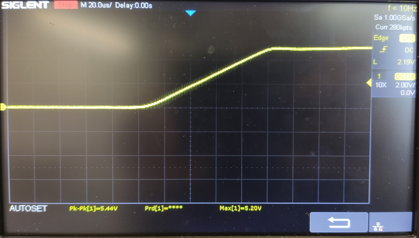
I've verified that the regulator works as intended and its output voltage raises almost linearly from 0V to 5V over ~100us (see image)

enter image description here

Disconnecting the 3V3 line while maintaining the 5V (the HAT was connected to the Pi with some M-F jumpers) makes the Pi boot correctly.

No bootloader settings (e.g. WAKE_ON_GPIO) change the behavior, shorting global_en to ground doesn't help either.

Is there a solution that would allow me to power the Pi AND get the 3V3 from it? Or at least a reason for this behavior?


Edit 1: I have a second copy of the PCB with only the power delivery circuitry populated (so no load on 3V3) and it works as intended (i.e. it powers the Pi, which boots correctly).


Edit 2: I've verified the behavior with another fully populated unit of my custom HAT and another unit of the RPi (revision 1.1 as well) - it doesn't boot either, nor does any combination of a HAT + RPi.

I'm planning on testing whether a newer revision or RPi will work, but first I've got to get a hold of one and I haven't seen any seller marketing theirs as a specific version.

For now I've worked around the issue: I've cut the 3V3 line from the Pi and mod-wired in an AMS1117 3V3 LDO. However, this is a workaround and not an answer.


Edit 3: I've managed to get an 8GB version of the RPi4 (they only come in the 1.4 revision) - still the same behavior.


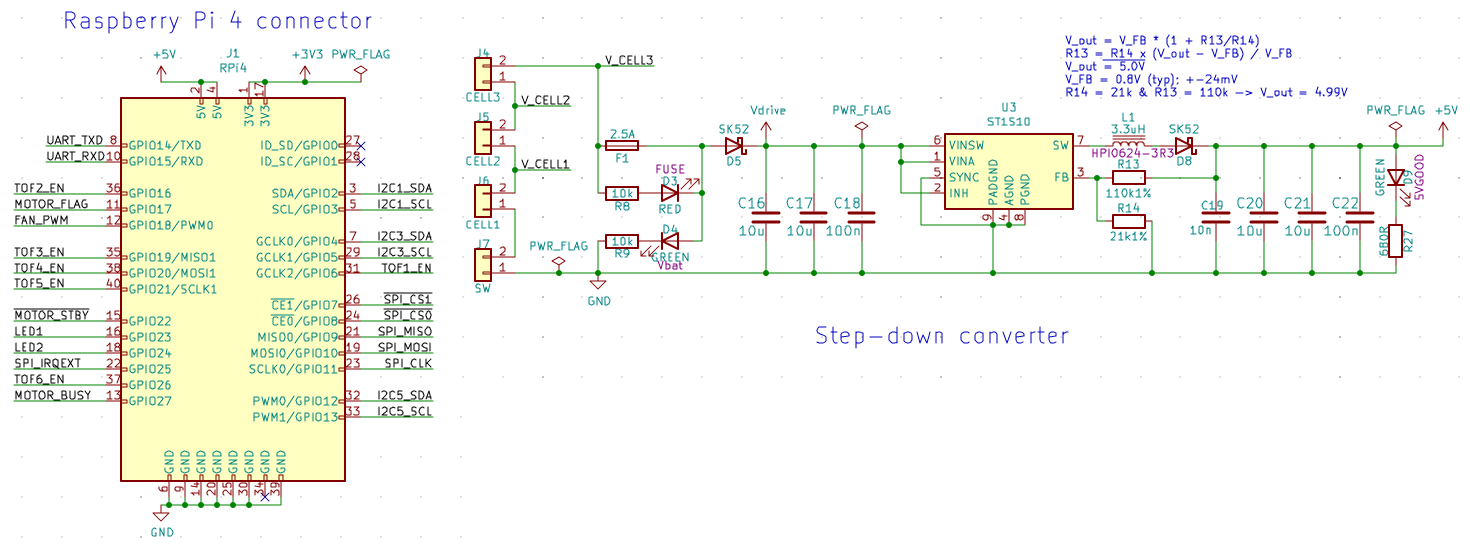
Edit 4: The schematics are available on github here (KiCAD) and the power delivery part is included below: power delivery part of the schematic
9
  • 1
    Does your custom hat use a printer circuit board or wires? How thick are the traces / wires the provide power?
    – CoderMike
    Commented Apr 28, 2021 at 19:52
  • It's a custom PCB. The 5V rail traces are 1mm thick and the regulator is less than 2cm from the 5V pins of the Pi.
    – MJBogusz
    Commented Apr 28, 2021 at 19:56
  • You could solder additional wires to test if increased thickness would help?
    – CoderMike
    Commented Apr 28, 2021 at 21:24
  • The voltage measurements were at the Pi's pins, so the voltage drop shouldn't be the issue here. I add some wires just to make sure though.
    – MJBogusz
    Commented Apr 29, 2021 at 12:41
  • You would need an oscilloscope to accurately measure the voltage, it can change very rapidly. 1mm sounds very small for potentially 3Amps.
    – CoderMike
    Commented Apr 29, 2021 at 12:43

2 Answers 2

1

It's likely that your HAT has some components that can "back power" the 3V3 rail (e.g. an IC that uses both 5V and 3V3, and has a leak current into 3V3 rail when it only gets power from 5V rail). The PMIC on RasPI will refuse to power-up if there is an existing voltage detected on its output.

Try checking the 3V3 rail on your HAT when it's powered but not connected to the Pi, and if there is a voltage above ~250mv it will cause the PMIC on Pi to refuse working.

3
  • This actually sounds plausible. Commented Sep 28, 2022 at 11:28
  • Plausible, but it's not the case here - I've re-verified with the schema and the components either use 5V or 3V3 exclusively.
    – MJBogusz
    Commented Sep 29, 2022 at 14:07
  • Then I'm not sure what's the exact cause, since this is what I encountered earlier this year and had exactly the same behaviour as yours. However taking a measure won't hurt anything, since sometimes leakage cuurrent can appear in very wierd ways, especially when dealing with diodes and capacitors alike. (In my case it was through a photodiode&capacitor array in a sensor IC) Commented Oct 1, 2022 at 14:29
1

Generating your own 3.3V is actually the most advisable solution, even if you manage to get your solution to work. It makes the power-on sequence of your product independent of the Pi, thus avoiding situations where your product suddenly stops working with a new version of the Pi. As you said yourself, it may be very hard for customers to know which HW version they are getting in the first place, so if their Pi won't work with your HAT, they will blame you.

If you want to diagnose the startup sequence, I suggest you hook up the scope on 5V, 3V3 RUN and GLOBAL_EN lines. Then you should take a measurement while powering up your Pi via the USB jack, and another one where you power it via your HAT. Either you will see voltage on 3V3 appear earlier in the second measurement (confirming the theory from the other answer), or something else will look differently.

Note that the Pi knows when it's powered via USB thanks to PD_SENSE. As an experiment, you could short it to VBUS and see if the Pi will start when powered by your HAT.

1
  • 1
    That's a good guideline to debugging RPi powerup. Unfortunately I'm not involved in this particular project anymore, but I'll forward this information to the people continuing the works and I'll update here if I'll learn anything. Also, just like you suggest, I've since switched to generating my own 3V3 in all of my RPi-related projects.
    – MJBogusz
    Commented Sep 29, 2022 at 14:27

Your Answer

By clicking “Post Your Answer”, you agree to our terms of service and acknowledge you have read our privacy policy.

Not the answer you're looking for? Browse other questions tagged or ask your own question.