0

I'm trying to read the output of a photodiode sensor circuit by the Pi GPIO. The sensor circuit outputs roughly 3.3v, from an Op Amp when the sensor detects IR. Circuit Diagram:
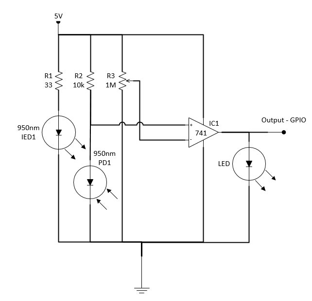
Sensor Circuit

N.B Op amp is a 358, not 741

Currently using this code on the Pi:

#!/usr/bin/python

import RPi.GPIO as GPIO
import os
import time

GPIO.setmode(GPIO.BOARD)
#GPIO.setup(16, GPIO.IN)
GPIO.setup(16, GPIO.IN, pull_up_down = GPIO.PUD_DOWN)
#prev_input = 0
GPIO.setup(26, GPIO.OUT)
GPIO.output(26, 0)
while True:
    #input = GPIO.input(16)

    if (GPIO.input(16) ==1):
        print("ON")

    elif (GPIO.input(16) ==0):
        print("OFF")

    time.sleep(0.25)

    os.system('clear')

The output on the screen fluctuates between "ON" and "OFF".

As a test: If I plug the 3.3v of the Pi into a GPIO and read the input, I get a stable 'ON' state. Similarly, plugging into GND/disconnecting, I get a stable 'OFF' state.

I welcome any suggestions! Hope this edit helps make more sense?

9
  • Just to be sure: GNDs of both systems are properly connected? Arduino output levels are 3.3V?
    – Ghanima
    Commented Dec 12, 2014 at 13:22
  • The logic level of most Arduinos is 5 volt and the Pi is 3.3v volts. You could seriously harm your Pi connecting them directly (without a logic level shifter in between). Commented Dec 12, 2014 at 13:22
  • As per my edit (sorry for not clarifying before), 3.3v input to the Pi doesn't work either.
    – gunnarain
    Commented Dec 12, 2014 at 13:32
  • 1
    I'm confused. Could you edit your post to indicate what you are actually trying to achieve (the end goal) and what isn't working?
    – joan
    Commented Dec 12, 2014 at 13:34
  • Apologies for further confusion, hopefully my second edit clarifies?
    – gunnarain
    Commented Dec 12, 2014 at 13:55

1 Answer 1

1

Rather than adding another comment to the confusion above (I am still not sure what you are asking), there are problems with your circuit design.

The op-amp will act as a comparator, but near the changeover point will make the circuit sensitive to minor changes in voltage and/or light level.

You should use a Schmitt trigger. This can either be a dedicated Schmitt trigger, or you can configure the 741/358 with some positive feedback (look at Wiki for examples). You don't actually need this, as Pi GPIO can be configured with Schmitt-trigger filtering.

What is the LED on the output supposed to be doing? It will clamp the output (which is probably protecting your Pi from damage when the output swings to +5V), but without a limiting resistor will overload the op amp

Your Answer

By clicking “Post Your Answer”, you agree to our terms of service and acknowledge you have read our privacy policy.

Not the answer you're looking for? Browse other questions tagged or ask your own question.