0

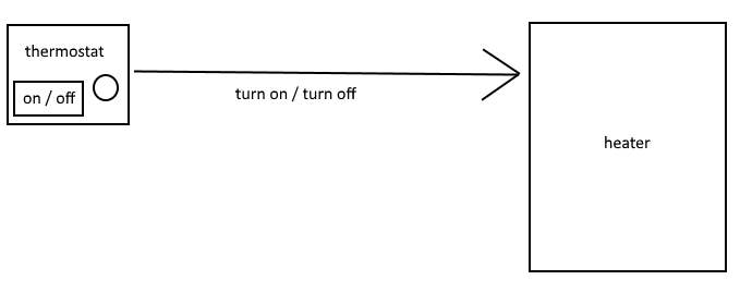
Currently the heating system in my house works as outlined in the following diagram. I push a button on the thermostat which will either turn on or turn off the thermostat. When the thermostat is turned on, the thermostat will turn send a signal to the heater to turn on or off depending on the temperature.

enter image description here

I want to use my Raspberry Pi (the original Raspberry Pi Model B (512MB RAM)) to be able to program a timer so the system can be a bit smarter and I can be warm in the mornings.

I want the RPi to send an on / off signal to the heater based on some logic that I can define. I am a skilled software developer and intend to refer to the many open source gpio software solutions available in developing the logic. However, I have 0 experience with gpio so I thought I'd ask here if 1) this is feasible, and 2) what pins I need to be concerned with.

The cable connecting the thermostat to the heater is simply a set of 2 copper wires, the live and (I presume) neutral. My intention is to cut the wire (this is actually already done, accidentally, and soldered back together), and attach the cut ends to the gpio.

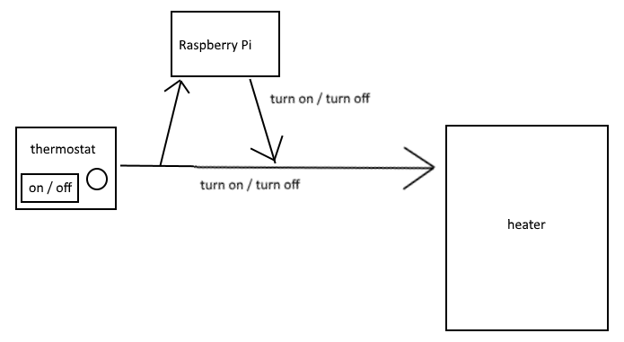
I also want the original thermostat functionality to remain intact. The following diagram is a basic outline of what I'd like to achieve

enter image description here

The questions I have are

  • What pins of the gpio do I need to connect the ends of the wire to?
  • What does the logic need to trigger in regards to these pins? e.g. I want the heat to turn on at 5 AM. The timer event fires, and uses a _gpioService to do something which ultimately sends a signal to the heater to turn on. What is a basic outline of what the _gpioService needs to do to send the signal?
7
  • If the wires between the thermostat are live and neutral (i.e. mains) you should not solder either of them together to mend a break (my understanding). You need to replace the wire.
    – joan
    Jun 1, 2017 at 7:11
  • If you are unqualified you SHOULD NOT interfere with mains wiring. This question has little to do with the Pi. Your assumption that the wires are live and neutral is almost certainly false.
    – Milliways
    Jun 1, 2017 at 8:15
  • @Milliways By the looks of this, those aren't the mains for the heater. Most likely, they are 18ga pair carrying 24v that simply triggers the relay in the heater that enables the mains. That's a guess though. OP, if that's the case, you need a relay that operates at 3.3v for the action side (that connects to GPIO), and minimum of 24v on the heater side. Then you simply toggle the specific GPIO pin to turn the heater's internal relay on/off.
    – stevieb
    Jun 1, 2017 at 16:05
  • @stevieb, I think you are correct, though I'm unsure about the voltages. Both the heater and the thermostat operate on their own power supply. The wire I'm referring to in this case simply sends a signal from one to the other. I'm sure of this because when the wires were cut I was still able to send a signal to the heater to get it to turn on, and then disconnect the wires.
    – DaveDev
    Jun 1, 2017 at 22:36
  • 1
    @DaveDev You still need a relay (or some other form of level shifter). The GPIO is capable of 3.3v maximum. Applying any more than that can and will fry your Pi.
    – stevieb
    Jun 2, 2017 at 11:53

2 Answers 2

1

Your question can not be answered in a useful way because you have not given enough basic information. Specifically, you've not stated what the "signal" is between the thermostat and the heater. For example, is the "signal" a contact closure via mercury switch inside the thermostat? Or, is it, as some have guessed, an "active signal" of 24v, or even mains/ac voltage? Or, is it something else? Have you got a volt/ohm meter, or know someone who does?

My answer comes approximately 21/2 years after you have asked your question. I'm going to make an assumption that you've moved on or lost interest in this project. However, if the missing information were supplied (or one could make a reasonable assumption) this would be an "answerable" question. And so, if you're still out there & interested in moving this forward, please let us know.

0

You should isolate your Pi from this circuit. It is likely that mains current is involved which leads to the go-to solution of

  • Relays : They are easy to understand , increase safety , are cheap and get the job done. Use a readymade relay board since playing with mains can kill.

https://www.variantweb.net/blog/building-a-thermostat-with-the-raspberry-pi/

Your Answer

By clicking “Post Your Answer”, you agree to our terms of service and acknowledge you have read our privacy policy.

Not the answer you're looking for? Browse other questions tagged or ask your own question.