2

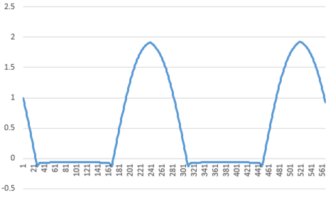
I'm using this Raspberry Pi High-Precision AD/DA Expansion Board from waveshare. I have some questions regarding its ADC (model name: ADS1256) unable to give out negative value. Specifically, only giving out negative values around -0.1V. Here are details of my problem.

Current situation:

  1. Using the user manual provided with the board, I have managed to read analog input data from on-board potentiometer and LDR (converted to digital data) using their sample codes. In order to use the on-board potentiometer and LDR, I've connected jumpers to the appropriate positions as metioned in the manual.

  2. Now, I've connected a function generator, sending out +/-2V amplitude of analog sine wave signal, to the waveshare board.

  3. By modifying the sample code provided, I've printed out the converted data and ploted them, which is the figure shown below (y-axis = voltage, x-axis = number of data)

enter image description here

  • figure 1: sine wave plot

Here are the questions:

  1. Is this normal phenomenon for this ADC board?

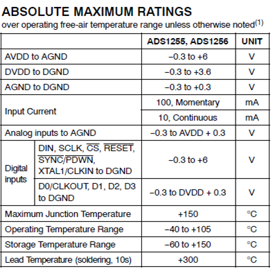
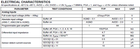
  2. If so, am I correct to assume that this ADC can only receive analog inputs above zero? (I've looked through the ADS1256 datasheet and studied a bit, but had hard time understanding the input range found in the document, shown below.)

  3. If above assumption is true, then can the analog input range be changed?

enter image description here enter image description here

  • figure 2: datasheet screenshots, page 2 and page 3

Any kind of help or comment would be greatly appreciated. Thanks!

Product page: https://www.waveshare.com/wiki/High-Precision_AD/DA_Board

Manual : https://www.waveshare.com/w/upload/b/b7/High-Precision-AD-DA-User-Manual.pdf

Sample codes : https://www.waveshare.com/wiki/File:High-Precision-AD-DA-Board-Code.7z

ADC datasheet : https://www.waveshare.com/wiki/File:ADS1256.pdf

5
  • This question is unrelated to the Pi. Unless you power the ADC with ± voltages it is unlikely to support negative input. Frankly from the product page you wouldn't know what it does. The extract from the datasheet you quoted indicates you are exceeding the maximum input voltage.
    – Milliways
    Commented Mar 27, 2019 at 6:02
  • @Milliways Thanks for the response. I'll try to find a way to power the ADC with +/- voltage. Also I'll redirect this question in the signal processing part.
    – Jihun Kim
    Commented Mar 27, 2019 at 6:30
  • This is unlikely to work. You need an ADC designed to separate Analog input and digital output. There are established techniques to offset input DC - but you need to ask on an EE site (and be clearer about what you are trying to achieve).
    – Milliways
    Commented Mar 27, 2019 at 6:34
  • @Milliways Alright. I've heard of offsetting input DC before. Can this be done by manipulating with registers of the ADC? Meanwhile, I'm not quite sure what you mean by EE site. Could be provide me with a link or what the EE stands for?
    – Jihun Kim
    Commented Mar 27, 2019 at 6:40
  • electronics.stackexchange.com
    – Milliways
    Commented Mar 27, 2019 at 6:48

2 Answers 2

2

am I correct to assume that this ADC can only receive analog inputs above zero?

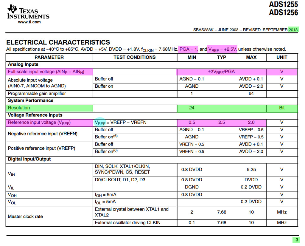
Well, the datasheet says the analog input range is + - (Vref * 2) / PGA. In other words, if you set Vref = +2.5V, PGA = 1, then the input range is +-5V.

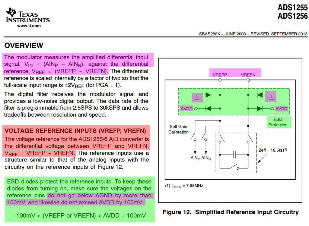
Though you can input +-5V, what is measured depends on Vrefp and Vrefn, as described in the overview.

enter image description here

enter image description here

1
  • Thanks. With your comment, I'll look into this matter in depth.
    – Jihun Kim
    Commented Mar 27, 2019 at 9:34
2

Your ADC isn't working because you're exceeding the ABSOLUTE MAXIMUM RATINGS listed in your question:

Analog inputs to AGND: −0.3 to AVDD + 0.3 (V)

In other words, this ADC cannot measure negative voltages. Most simple ADCs can't do that.

You could overcome the problem by adding a constant offset voltage to your signal (google "Non-Inverting Summing Amplifier"), then subtract this known offset from the ADC measurement in software. Or, if electronics is not your strong side, you could simply put the signal through a resistor divider attached to AVDD: a 2x divider will let you measure voltage from +AVDD to -AVDD:

schematic

simulate this circuit – Schematic created using CircuitLab

Your Answer

By clicking “Post Your Answer”, you agree to our terms of service and acknowledge you have read our privacy policy.

Not the answer you're looking for? Browse other questions tagged or ask your own question.