BY the looks of the schematic the GPIO pins are connected to +5v Maybe it does work but I would not recommend that it.
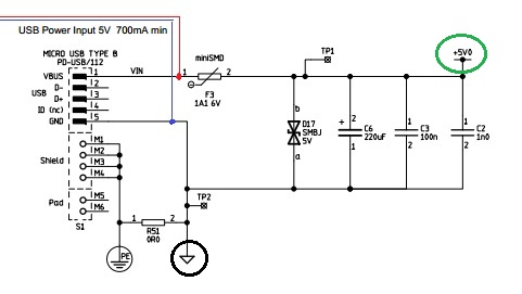
I have copied part of the input schematic. Just solder your barrel plug to the parts after the USB input. (Red +5v, Blue GND) You can also see the end of the circuit connects to +5v bus (green circle) after the filtering capacitors.

WHY?
Because the power is smoothed making it better for the CPU/GPU - it also hard fused in case of some short circuit and the POWER LED will indicate power.
The GPIO pins should only be used to power external components. ( I cannot tell clearly where the +5 on GPIO goes but I can tell you that it is fused properly)
ALTERNATIVE
It is not ideal but you can connect +5v to the TP1 and GND to TP2 (TP = Test Point)
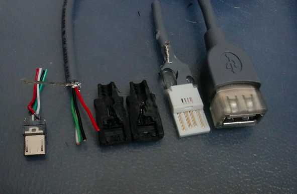
Cut the micro USB cable and use the RED and BLACK colour coded cables and connect it to your power adapter. Using power adapters that are rate more than 1AMP (1000ma) is fine. The Raspberry Pi will not use more than 800ma any way- But the voltage HAS to be 5votls

