7

I'm working on using the Raspberry Pi Zero camera as well as other sensors simultaneously. But while trying to figure out which GPIO pins the camera uses, so I know which ones I have left for other sensors, I couldn't find any documentation stating which pins are actually used by the camera.

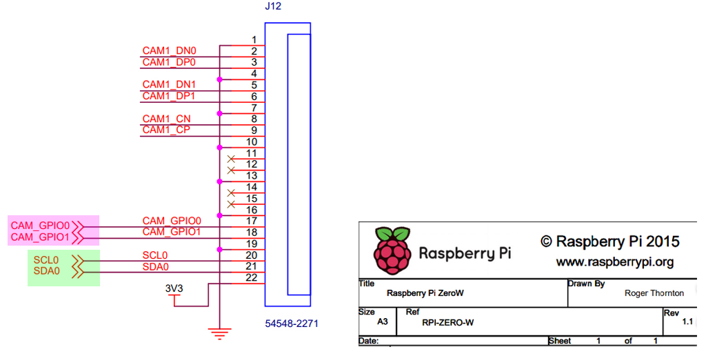
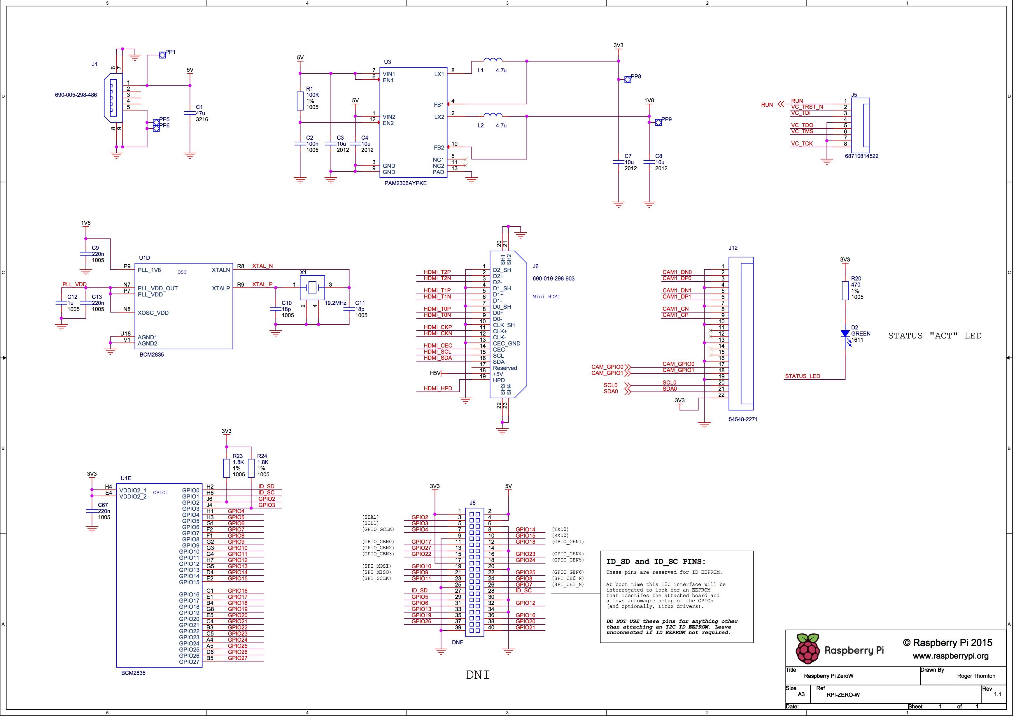
I found this diagram, which on the middle row, right column shows that the CAM1_DN0, CAM1_DP0, CAM1_DN1, CAM1_DP1, CAM1_CN, CAM1_CP, CAM_GPIO0, CAM_GPIO1, SCL0, and SDA0 pins join some connector, but other than SCL0 and SDA0 none of these names match pins on the pi.

Raspberry Pi Zero Schematic

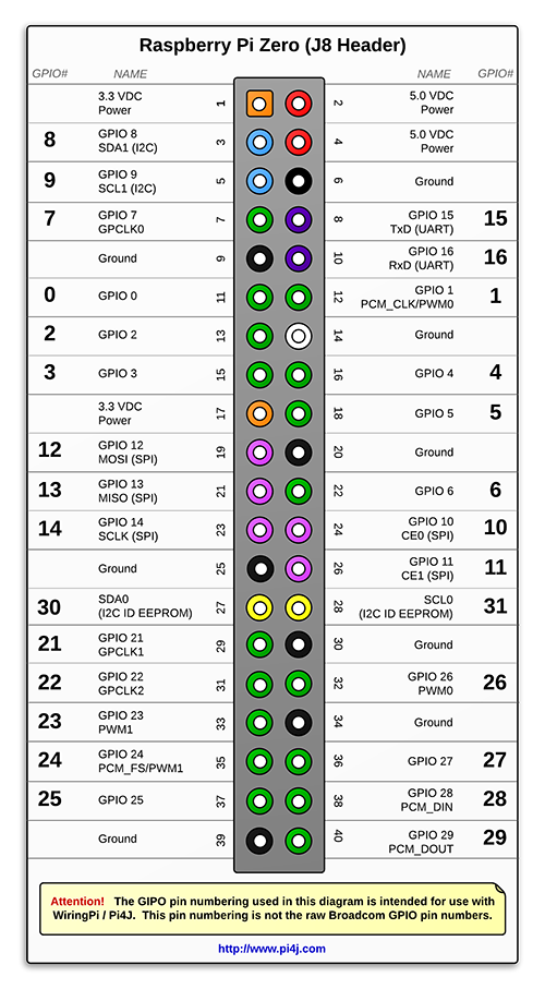
Further, this chart says that SCL0 and SDA0 correspond to pins 27 and 28 on the pi, but the above chart states that those two pins are "reserved for ID EEPROM":

Apparent Raspberry Pi Zero Pinout

There seems to be lots of conflicting information on what pins are used by the camera connector, and what pins can safely be used when the camera is installed.

1
  • 2
    The CSI connected camera doesn't use ANY GPIOs out of the ones you have on the 40-pin header.
    – Dougie
    Commented Nov 4, 2019 at 13:08

4 Answers 4

5

The camera does NOT use any of the pins on the expansion header, so all normal listed pins are available for use.

Pins 27, 28 (SDA0, SCL0) are RESERVED for HATs (and other internal purposes) so are UNAVAILABLE on ALL models and are shared but this is undocumented.

2

Question

Which GPIO pins does the Pi Zero camera use?


Answer

Rpi camera uses GPIO 0, 1, and also I2C 0.

Notes

I think GPIO pins 0, 1, and I2C 0 are for OS to use. Users should not use them.

I did once extracted the I2C 0 physical wires out and tried to fiddle with I2C 0 bus signals, because I did not have enough I2C buses to use. But that is risky.

I also read that Rpi3B+ can setup more than one I2C bus, using device tree overlays. I tried and found no tutorials worked. Those who claimed it worked, including one popular "instructable", never specified the Rpi hardware and software used. So I think those tutorials were not reliable or fake.

Now the good news is that Rpi4B has 5 I2C buses. I tried and found them reliable.

So my suggestion to newbies is NOT to use the GPIO pins (0, 1) and I2C bus (0).

In the new Rpi4B, there are more I2C buses for you to play with.

And there is also no reason to use hijack systems GPIO pins 0, and 1, because you can always use GPIO extenders such as MCP23017/MCP23S17 to get many more GPIO pins.

MCP23017's GPIO pins can also do many fancy interrupt functions, much more powerful than Rpi GPIO interrupt pins. You can also connect many MCP23017 modules and so you can easily get 64 or more GPIO pins. One good thing with MCP23x17 is that you can use either I2C or SPI, or both!

You can also use PWM controllers such as PCA9685. PCA9685's 16 PWM GPIO pins again give you more flexibility than the few Rpi GPIO PWM pins. The PWM pins can can actually be used as GPIO pins, if you set duty cycle to 100%. Again you can also place many PCA9685 on one I2C bus, to get more than 64 PWM / GPIO pins to use.


rpizw cam gpio i2c


References

(1) Using multiple I2c buses on Rpi4B


End of Answer

1

CAM_GPIO0 -> GPIO44
CAM_GPIO1 -> GPIO40
(ref https://github.com/torvalds/linux/blob/master/arch/arm/boot/dts/bcm2835-rpi-zero-w.dts line 87 91)

SCL0 -> GPIO29
SDA0 -> GPIO28
(ref https://elinux.org/RPi_BCM2835_GPIOs)

1
  • 3
    Please make this answer a little more verbose, as it is not very intuitive.
    – user96931
    Commented Apr 29, 2020 at 21:31
0

Gonna try 1, 2 5, on the left. and ond sdi. Hopr that works also. Honestly i have no idea and problably end up programming myself mad. Still

Your Answer

By clicking “Post Your Answer”, you agree to our terms of service and acknowledge you have read our privacy policy.

Not the answer you're looking for? Browse other questions tagged or ask your own question.