I'm working on using the Raspberry Pi Zero camera as well as other sensors simultaneously. But while trying to figure out which GPIO pins the camera uses, so I know which ones I have left for other sensors, I couldn't find any documentation stating which pins are actually used by the camera.
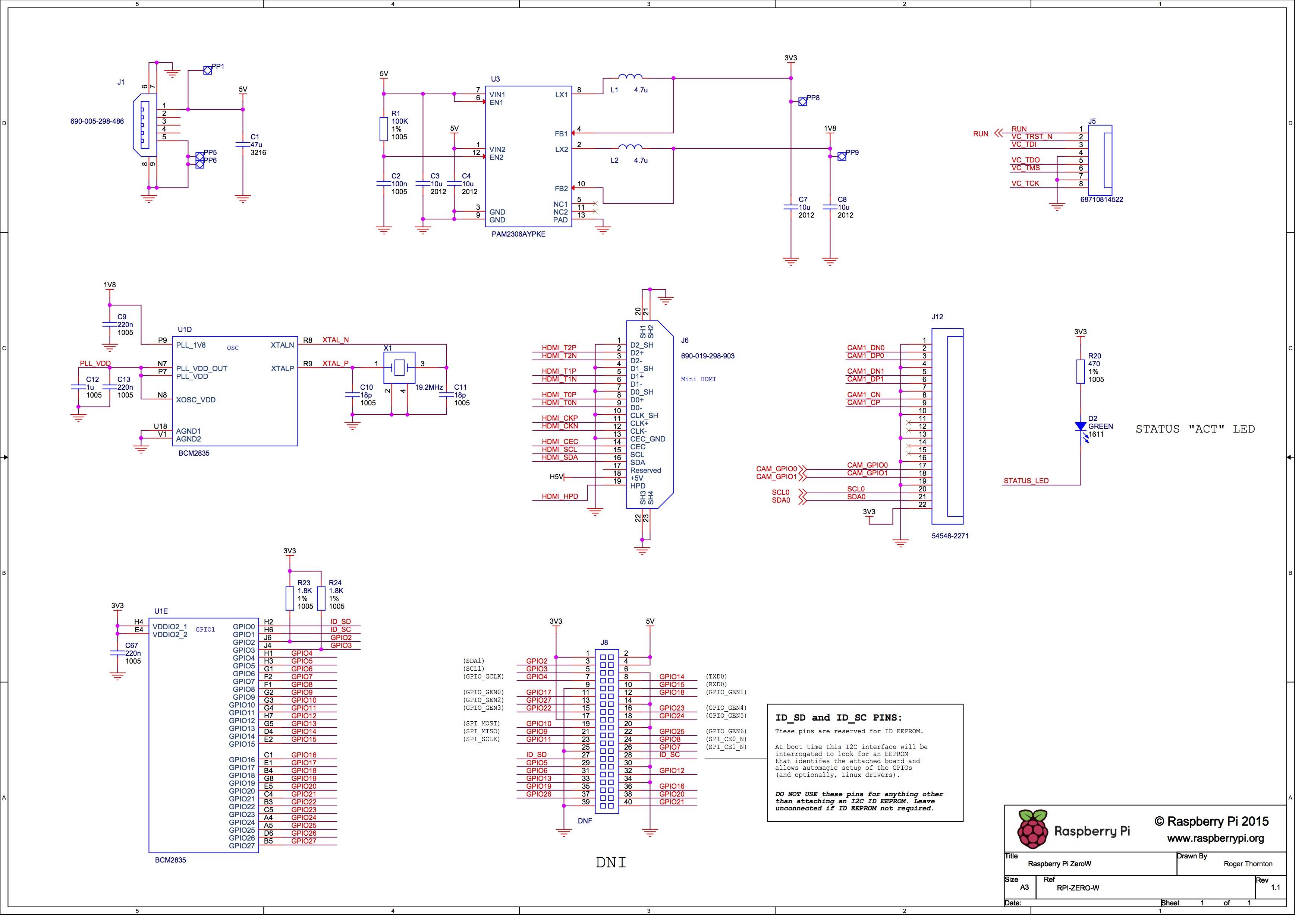
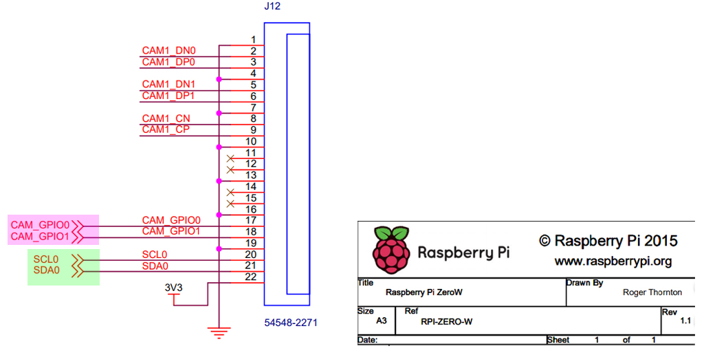
I found this diagram, which on the middle row, right column shows that the CAM1_DN0, CAM1_DP0, CAM1_DN1, CAM1_DP1, CAM1_CN, CAM1_CP, CAM_GPIO0, CAM_GPIO1, SCL0, and SDA0 pins join some connector, but other than SCL0 and SDA0 none of these names match pins on the pi.
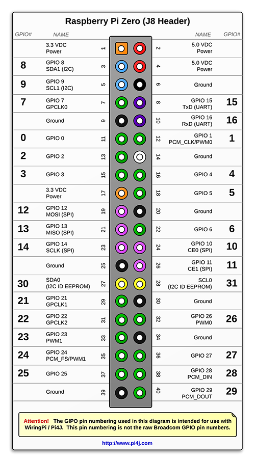
Further, this chart says that SCL0 and SDA0 correspond to pins 27 and 28 on the pi, but the above chart states that those two pins are "reserved for ID EEPROM":
There seems to be lots of conflicting information on what pins are used by the camera connector, and what pins can safely be used when the camera is installed.


