1

I have an IR pyroelectic flame sensor which detects flames within the 8-10hz of flame flicker. I am new to the ADC world so any help is very appreciated.

Documentation: https://pyreos.com/wp-content/uploads/2020/11/Pyreos-Analog-TO-Flame-Sensor-One-Channel.pdf

I have the py0573 which has a bandpass filter for CO2 spectrum. According to the company's algorithm recommendation, I basically need to plot/detect FFT (Fast Fourier transform) bins from the 5-15hz frequency to determine a "flame" exists on the FOV of the sensor.

In order for me to read the signal from the half-rail, I installed a MCP3008 to my RPi model 4 and set the signal to CH0 of the ADC. I also included a .1uf decoupling capacitor.

Using the below code, I am able to get some readings from the sensor, but I am unsure if this sampling rate is setup correctly or not.

Questions:

  1. How do I setup the read from the ADC within the 8-10hz range?
  2. Is there a way to plot this with FFT? Do I need FFT or can I determine the total sum values from ADC to indicate a "flame"?
  3. Is the frequency setup basically the loop speed of Python or the spi.max_speed_hz option?
  4. Am I converting the raw ADC values correctly using numpy interp?
  5. If the sensor has a max 10hz frequency then I need to double that for my sample rate?
  6. Should I be using Adafruit's adafruit-circuitpython-mcp3xxx package instead?

With the below code, I am able to see the values change when I light a flicker match but its a bit inconsistent and only changes when the flame is flickering and not when its still.


import spidev 
from numpy import interp
import time
import datetime
from datetime import timedelta

# Start SPI connection
spi = spidev.SpiDev() # Created an object
spi.open(0,0)   


# Read MCP3008 data
def analogInput(channel, hz):
  spi.max_speed_hz = hz
  adc = spi.xfer2([1,(8+channel)<<4,0])
  data = ((adc[1]&3) << 8) + adc[2]
  return data

data_list=list()
init_time = datetime.datetime.now()


while True:
    
    
    output1 = analogInput(0, 1000000)
    output1 = interp(output1, [0, 1023], [0, 100])
    
    data_list.append(output1)
    if init_time < datetime.datetime.now() - timedelta(seconds=2):
        
        print("min" + str(min(data_list)))
        print("max" + str(max(data_list)))
        print("avg" + str(sum(data_list)/len(data_list)))
        data_list=list()
        init_time = datetime.datetime.now()
        
        
    time.sleep(.001)
    

1
  • 1
    Comments are not for extended discussion; this conversation has been moved to chat.
    – goldilocks
    Commented Mar 10, 2021 at 18:51

1 Answer 1

0

Question

How to use Rpi python MCP3008 ADC to help analyse flame flicker signals?


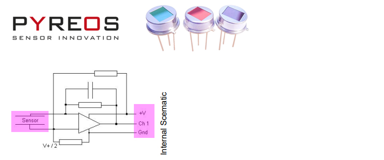
pyreos schematic

Notes

  1. A py0573 bandpass filter is used for CO2 spectrum

  2. To determine if a "flame" exists on the FOV of the sensor, the vendor recommends a plot/detect FFT bins from the 5-15hz frequency.


Electrical Characteristics

  1. Max. Voltage (+V) = 8.0 V

  2. Min. Voltage (+V) = 2.7 V

  3. Output voltage normalised around mid-rail

  4. Time Constant = ~12 ms

  5. Op-Amp with 10 GΩ feedback resistor


Answer

Part 1 - Using MCP3008 to read raw data

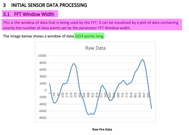
First thing first is to prepare 1,024 flame sensor readings for FFT. (See Reference 6 and Appendix B below for more details.)

FFT Raw Data


/ to continue , ...


References

(1) Thin Film Pyroelectric Flame Sensor - PY-ITV-FLAME–TO39(2+1) R5.2 - Pyreos

(2) MCP3008 SPI 2.7V 8-Channel 10-Bit A/D Converters - MicroChip

(3) Rpi Reading MCP3008 10 bit ADC Result Problem - Rpi SE 2019may22

(4) Flame Detector - Wikipedia

(5) Tips To Select The Right Flame Detector - Edward Naranjo, Emerson Automation Solutions 2019mar06

(6) AN0125 Application Note: Sample Flame Detection Ratio Based Algorithm - Pyreos

(7) Pyreos Evaulation Kit

(8) MCP3008 10 Bit ADC Raspberry Pi Python Library 0.1a3 (pip install mcp3008) - PiPy.org

(9) MCP3008/MCP3201/MCP3208 10-bit/12-bit ADC Rpi Python Programming / Demo Program / Q&A - tlfong01, EESE 2020aug06

(10) A Review on Forest Fire Detection Techniques - Ahmad A. A. AlkhatibFirst Published March 4, 2014 Review Article

(11) 32/64/128/256/512/1024/2048/4096 Point FFT Core - IPCores


Appendices

Appendix A - Pyroelectric Flame Sensor PY-ITV Datasheet Summary

Introduction

The Pyreos thin film pyroelectric infrared flame detectors offer exceptionally high responsivity, a wide field of view of typically 100° (*subject to filter band pass specification) and class leading rapid recovery from thermal and electrical shocks (<1 second downtime). This current mode sensor has excellent signal to noise at the signature 8-10 Hz flicker range of a flame, and can provide accurate discrimination of flame sources in triple IR flame detection systems.

The sensor element is built into a low noise circuit that has an internal CMOS op amp with a 10GΩ feedback resistor outputting a voltage signal centred around half the supply rail.


Sensor Characteristics

Filter aperture = 5.2 mm x 4.2 mm

Element size = 1000 µm x 1000 µm

Package = TO39

Responsivity = 1 150,000 V/W

D* = 3.5 x 108 cm√Hz/ W

Noise = Mean 70 µV√Hz

Field of View = Typical 100°


Electrical Characteristics

Max. Voltage (+V) = 8.0 V

Min. Voltage (+V) = 2.7 V

Output voltage normalised around mid-rail

Time Constant = ~12 ms

Operating Temperature = -40 to +85 °C

Storage Temperature = -40 to +110 °C

Op-Amp with 10 GΩ feedback resistor

Filter As per Filters Available table


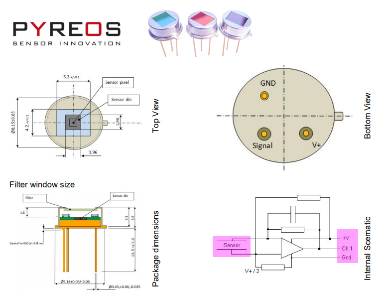
Appendix B - Package Info and Internal Schematic

package info and schematic


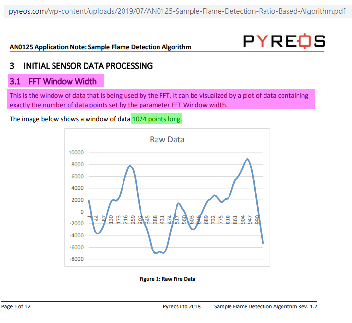
Appendix C - Example Raw Data for FFT

example raw data


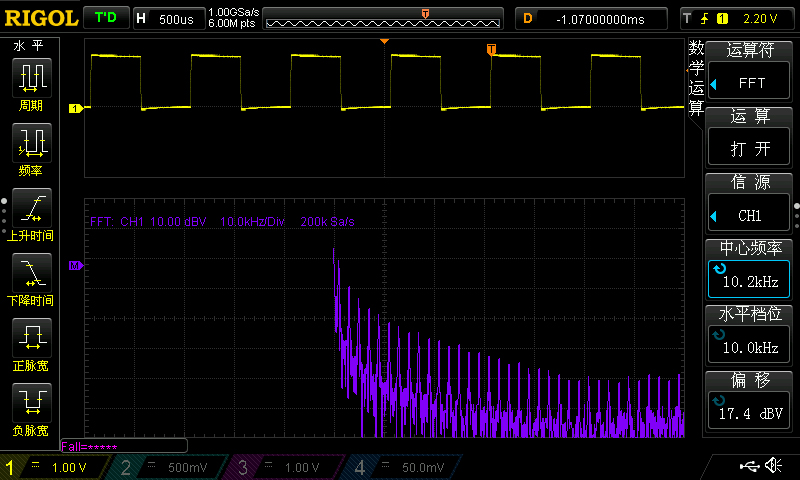
Appendix D - Rigol DS1504Z 50MHz 1Gsp/s Scope 1KHz square wave signal FFT Test

fft test

/ to continue, ...


Your Answer

By clicking “Post Your Answer”, you agree to our terms of service and acknowledge you have read our privacy policy.

Not the answer you're looking for? Browse other questions tagged or ask your own question.