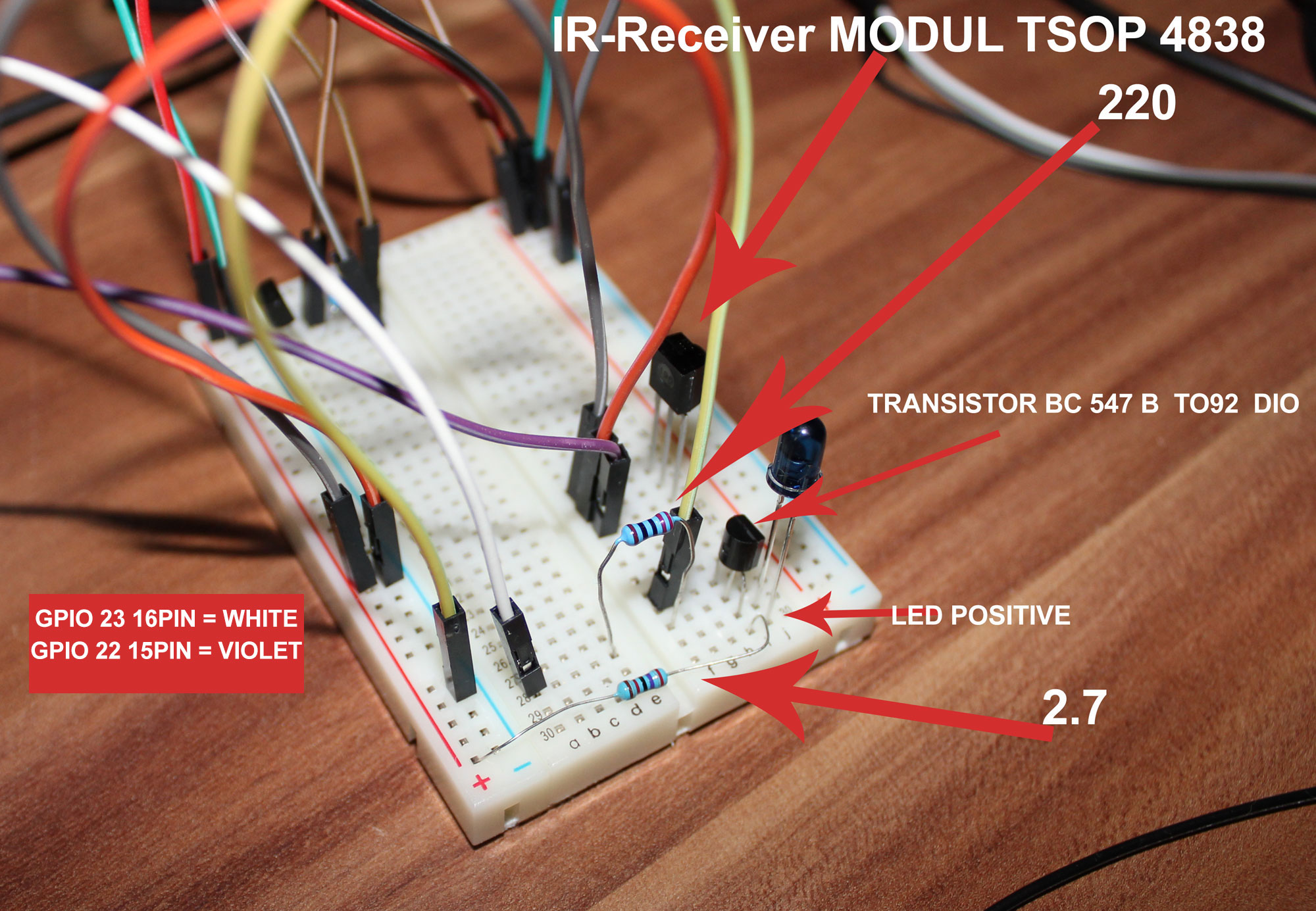
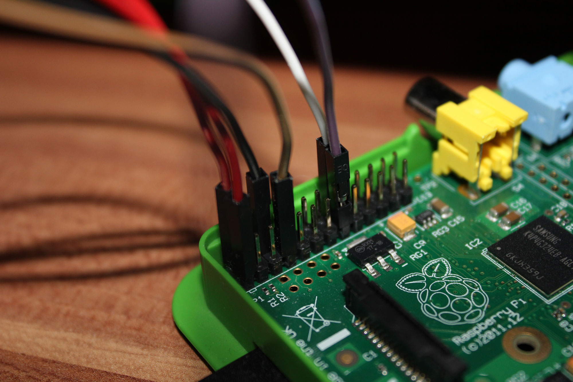
Config directory:
root@raspberrypi:/etc/lirc# ls
hardware.conf  lircd.conf  lircmd.conf
lircd.conf file
# Please make this file available to others
# by sending it to <[email protected]>
#
# this config file was automatically generated
# using lirc-0.9.0-pre1(default) on Wed Feb  3 22:32:04 2016
#
# contributed by
#
# brand:                       /root/SONY.conf
# model no. of remote control:
# devices being controlled by this remote:
#

begin remote

name  /etc/lirc/lircd.conf
flags RAW_CODES|CONST_LENGTH
eps            30
aeps          100

gap          45254

  begin raw_codes

      name KEY_VOLUMEUP
         2457     532     643     555    1211     584
          641     529     639     561    1156     665
          559     687     389     731     485     703
          395     813     185    1016     557     640
         1128

      name KEY_POWER
         2368     591    1060     733     558     666
         1129     692     506     614    1005     792
          556     693     557     644     528     599
          600     609     510     688     484     765
          786

  end raw_codes

end remote
lircmd.conf
#UNCONFIGURED
#
# To find out how to get a proper configuration file please read:
#
#   /usr/share/doc/lirc/README.Debian
hardware.config
########################################################
# /etc/lirc/hardware.conf
#
# Arguments which will be used when launching lircd
LIRCD_ARGS="--uinput"

# Don't start lircmd even if there seems to be a good config file
# START_LIRCMD=false

# Don't start irexec, even if a good config file seems to exist.
# START_IREXEC=false

# Try to load appropriate kernel modules
LOAD_MODULES=true

# Run "lircd --driver=help" for a list of supported drivers.
DRIVER="default"
# usually /dev/lirc0 is the correct setting for systems using udev
DEVICE="/dev/lirc0"
MODULES="lirc_rpi"

# Default configuration files for your hardware if any
LIRCD_CONF=""
LIRCMD_CONF=""
########################################################
cd /dev/ ls
autofs           loop2               ram0    tty    tty3   tty51      vcio
block            loop3               ram1    tty0   tty30  tty52      vc-    mem
btrfs-control    loop4               ram10   tty1   tty31  tty53      vcs
bus              loop5               ram11   tty10  tty32  tty54      vcs1
cachefiles       loop6               ram12   tty11  tty33  tty55      vcs2
char             loop7               ram13   tty12  tty34  tty56      vcs3
console          loop-control        ram14   tty13  tty35  tty57      vcs4
cpu_dma_latency  mapper              ram15   tty14  tty36  tty58      vcs5
cuse             mem                 ram2    tty15  tty37  tty59      vcs6
disk             memory_bandwidth    ram3    tty16  tty38  tty6       vcs7
fb0              mmcblk0             ram4    tty17  tty39  tty60      vcsa
fd               mmcblk0p1           ram5    tty18  tty4   tty61      vcsa1
full             mmcblk0p2           ram6    tty19  tty40  tty62      vcsa2
fuse             mmcblk0p5           ram7    tty2   tty41  tty63      vcsa3
gpiomem          mmcblk0p6           ram8    tty20  tty42  tty7       vcsa4
hwrng            mmcblk0p7           ram9    tty21  tty43  tty8       vcsa5
initctl          mqueue              random  tty22  tty44  tty9       vcsa6
input            net                 raw     tty23  tty45  ttyAMA0    vcsa7
kmsg             network_latency     rfkill  tty24  tty46  ttyprintk  vcsm
lirc0            network_throughput  shm     tty25  tty47  uhid       vhci
lircd            null                snd     tty26  tty48  uinput     xconsole
log              ppp                 stderr  tty27  tty49  urandom    zero
loop0            ptmx                stdin   tty28  tty5   vc-cma
loop1            pts                 stdout  tty29  tty50  vchiq
mode2 works too.
mode2 -d /dev/lirc0
Pulse's and space's are being showed. Also I have configurated .conf correctly as been told in instructions.
irrecord -d /dev/lirc0 ~/lircd.conf
cp ~/lircd.conf /etc/lirc/lircd.conf
Problem is that irw does not work. It outputs nothing after pressing my remote controller. irsend command outputs nothing too (checked led with camera, does not work)
irsend SEND_ONCE /etc/lirc/lircd.conf KEY_POWER
my /boot/config.txt:
dtparam=audio=on

# NOOBS Auto-generated Settings:
hdmi_force_hotplug=1
config_hdmi_boost=4
overscan_left=24
overscan_right=24
overscan_top=16
overscan_bottom=16
disable_overscan=0

dtoverlay=w1-gpio,gpiopin=4
dtoverlay=lirc-rpi,gpio_in_pin=22,gpio_out_pin=23
Any help or suggestions will be very big for me
********UPDATE*********
cat /sys/kernel/debug/gpio
prints
 GPIOs 0-53, platform/20200000.gpio, pinctrl-bcm2835:
 gpio-4   (w1                  ) in  hi
 gpio-16  (?                   ) out hi
Should it be a question-mark?
********UPDATE2********* Okey. Big changes. after Joan irw command now works. I have fresh generated lircd.conf file. now "irw" works and shows
root@raspberrypi:~# irw
0000000000000a81 00 KEY_POWER SONY
0000000000000a81 01 KEY_POWER SONY
0000000000000a81 02 KEY_POWER SONY
but
root@raspberrypi:~# irsend --device=/dev/lircd SEND_ONCE SONY KEY_POWER
root@raspberrypi:~# irsend --device=/dev/lircd SEND_ONCE SONY KEY_POWER
root@raspberrypi:~# irsend --device=/dev/lircd SEND_ONCE SONY KEY_POWER
root@raspberrypi:~#
does not work. What can I try now?


