1

I currently have this relay, and it is a 5V relay (for the control circuit).

Seeing as how our GPIO pins are rated at 3V3, I connected constant 3V3 power to Vcc and a GPIO pin to In1 to actually control the relay. This works well, but seeing as how this relay expects 5V to control it, I'm worried that 3V3 could be an issue of under-powering the relay (possibly causes unexpected disconnects from the magnet?).

With that being said, there doesn't seem to be any 3V3 relay modules out in the wild.

Are my concerns valid?

2 Answers 2

3

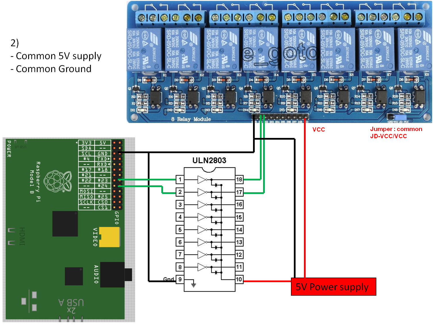
You are correct that 3.3 volts is unlikely to be enough to reliably activate the relay. You could use a uln2803 and a separate 5 volt power supply to control the relay. Something like this should work

enter image description here

13
  • So what that does is provide 5V for Vcc and 5V for In1? Is that correct? And thanks for your answer! Commented May 16, 2016 at 14:15
  • Exactly, but the uln2803 (darlington) also provides reverse EMF protection, which your relay board does not seem to have. Commented May 16, 2016 at 14:18
  • 1
    @ThomasStringer Yeah, current is not unlimited. Commented May 16, 2016 at 14:50
  • 1
    @ThomasStringer I am sure it has some spec for minimum activation current, it may not be printed on the relay but is included in the datasheet. Commented May 16, 2016 at 14:54
  • 1
    Yes, you could replace the darlington with a single transistor, and resistors, but I prefer the ULN2803 for exapnsion, price and ease of use. Yes, drawing to much current can damage the pin and/or the Pi. Commented May 16, 2016 at 15:17
-1

All you have to do is (1) connect 5v from the Pi to Vcc of the relay board. (2) connect ground from the Pi to Gnd of the relay board. (3) connect one of the many GPIO pins from the Pi to In1 of the relay board. Control this pin via a script you write on the Pi .

The relay requires 5v and ground to energize and 3v3 to control it.

9
  • 1
    "The relay requires 5v and ground to energize and 3v3 to control it." That's not the behavior I'm seeing. In my testing/experience, Vcc needs to equal In1 in voltage. Commented May 16, 2016 at 16:07
  • 1
    There's no indication that relay uses a 3.3v control. Especially since it is being marketed for Arduino AVR. There are 3.3V control relays, but I think these usually have a ULN darlington array IC (such as the one Steve is talking about) onboard. They are fairly large (1+ cm long) and easy to notice. They are also very cheap to buy in a DIP package.
    – goldilocks
    Commented May 16, 2016 at 16:10
  • Your solution does not provide any back EMF protection to the Pin or the Pi. Commented May 16, 2016 at 16:24
  • @SteveRobillard is it me, or does this seem like a wrongly-labeled relay with 3V3 capabilities? amazon.com/4-Channel-Optic-Isolated-Trigger-Arduino-Raspberry/… Commented May 16, 2016 at 16:26
  • @goldilocks it actually doesn't seem like there are many options for a 3V3 control relay module: amazon.com/s/… Commented May 16, 2016 at 16:27

Your Answer

By clicking “Post Your Answer”, you agree to our terms of service and acknowledge you have read our privacy policy.

Not the answer you're looking for? Browse other questions tagged or ask your own question.