I have a USB controller that I want to connect to my Raspberry Pi 3. I don't want to use the port itself though. So is there any way to cut off the usb plug and solder the 4 wires directly to the board? If I can, what pins would each wire connect to?
-
Provided you never use the corresponding socket you can flip the board over and solder straight to the USB connector pads. Or are you looking for an extra USB socket in addition to the existing 4?– gooberingCommented Feb 28, 2017 at 20:39
-
1@goobering I am not trying to add another socket. I will try your first suggestions, but I am confused which pins on the Pi 3 to solder to since there are many for the USB sockets. Any help would be appreciated!– BADyoyo2Commented Mar 1, 2017 at 14:58
1 Answer
- The Pi 3 has two dual USB modules positioned side by side.
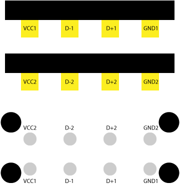
- Each individual socket in each module has 4 contacts:
- VCC (+5V for USB)
- Data -
- Data +
- Ground
- Each one of the 8 contacts in each module has a corresponding through-hole pin on the underside of the board.
Typically, if you cut open a USB cable you'll see red, white, green and black wires. These are:
- Red: VCC
- White: Data -
- Green: Data +
- Black: Ground
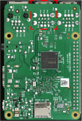
Get the board oriented this way:
The pins correspond as follows (duplicated on the second dual USB socket module):
A couple of cautionary points:
There's a not insignificant chance that, if you solder directly to the Pi, you may brick it. You'll 100% void the warranty and rule out returns in the process. Be careful about how much heat you're applying where, and for how long.
You might want to tape over/jam blue tack in/epoxy over/remove the USB sockets to prevent you from accidentally plugging things into them. I have no idea what might happen if you hook two devices into the same socket at the same time by accident, but I'd be inclined to err on the side of caution.
-
Thank you for you answer! I will be trying it soon, as my Pi just burned my SD card. So I'm trying to fix that problem. Thanks anyways!– BADyoyo2Commented Mar 1, 2017 at 16:12
-
Can confirm that this is the correct pinout, just used this to solder on some bulky USB warts to help make my build smaller. Commented Aug 12, 2020 at 15:10


