0

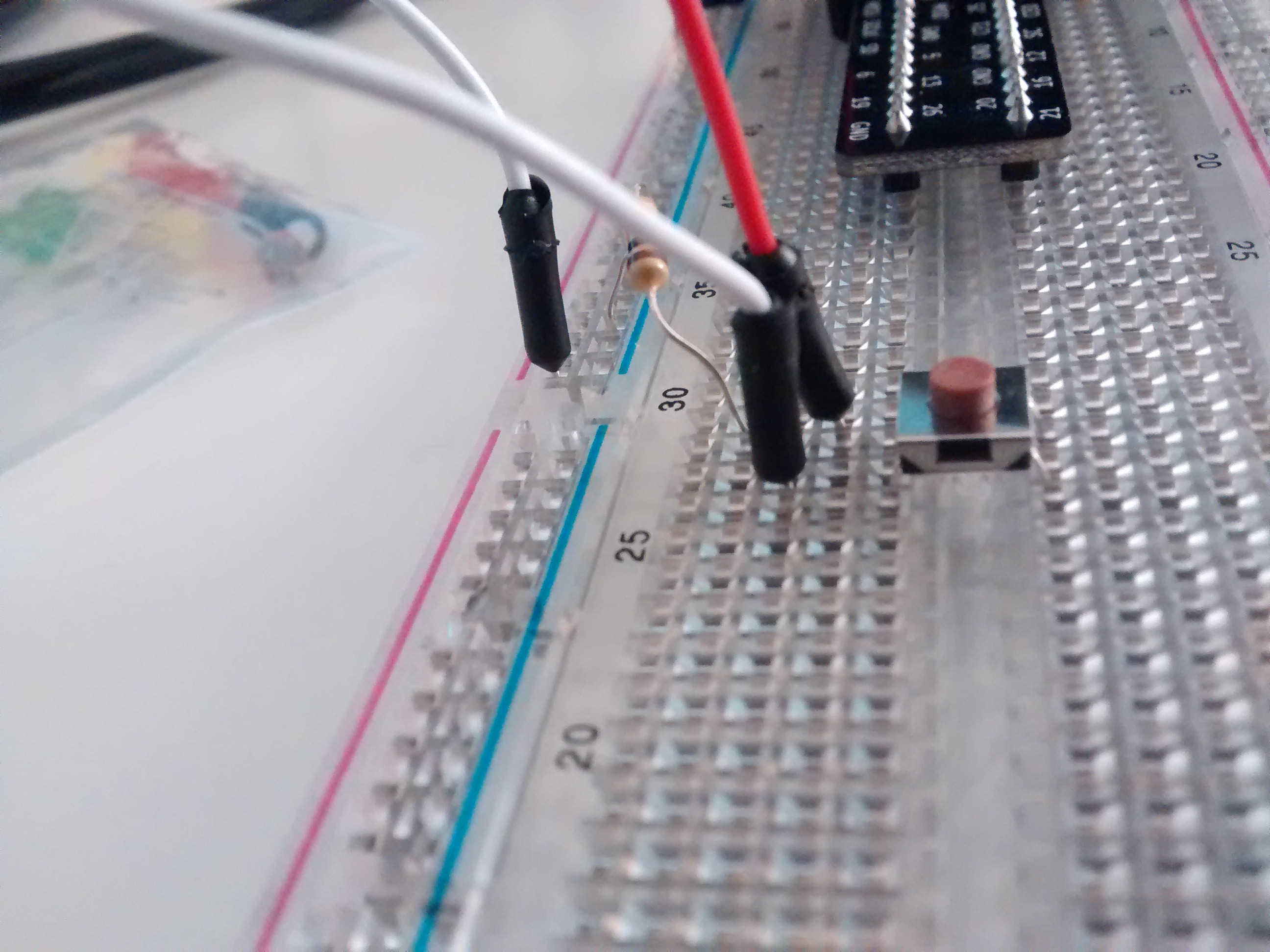
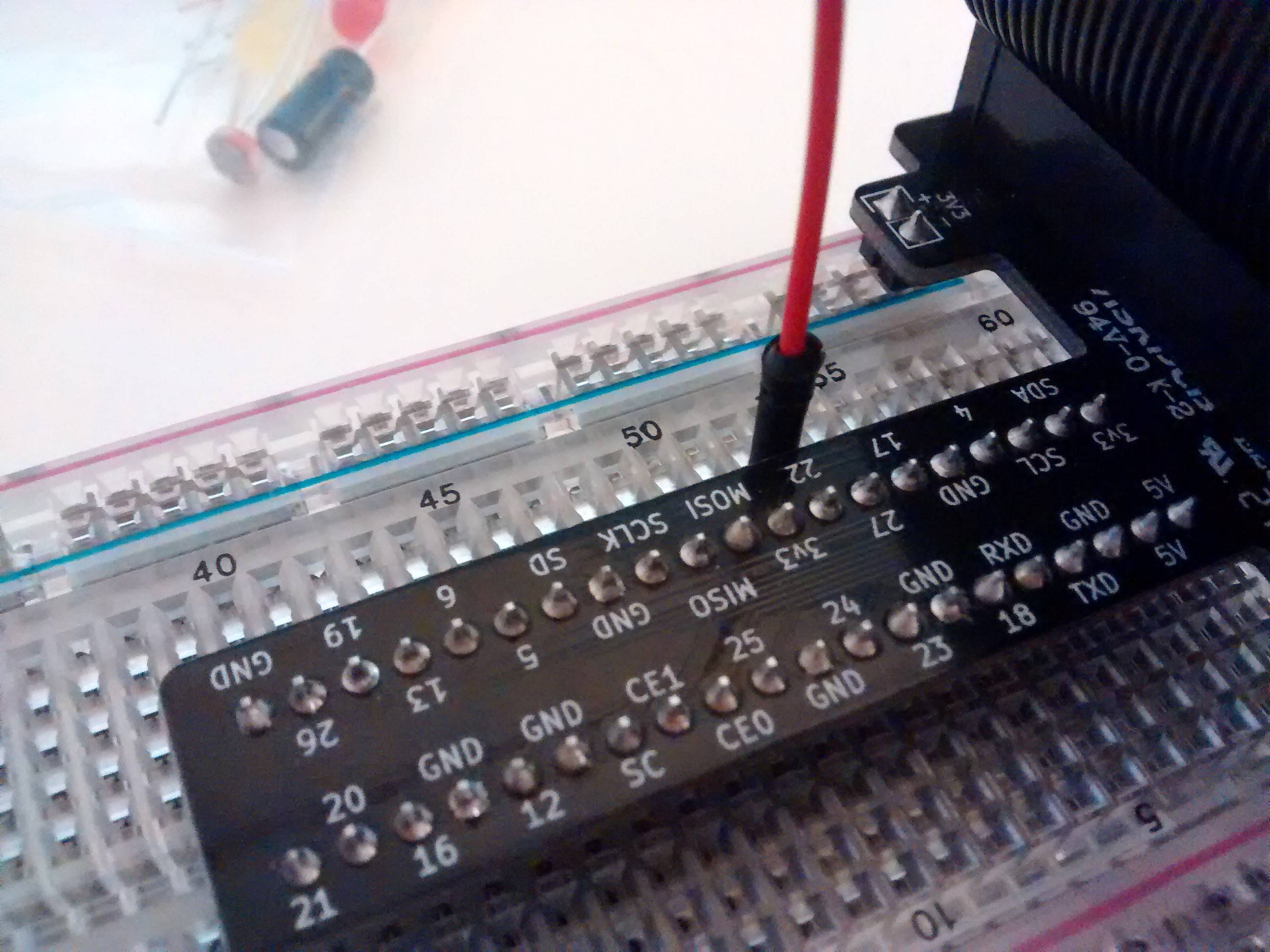
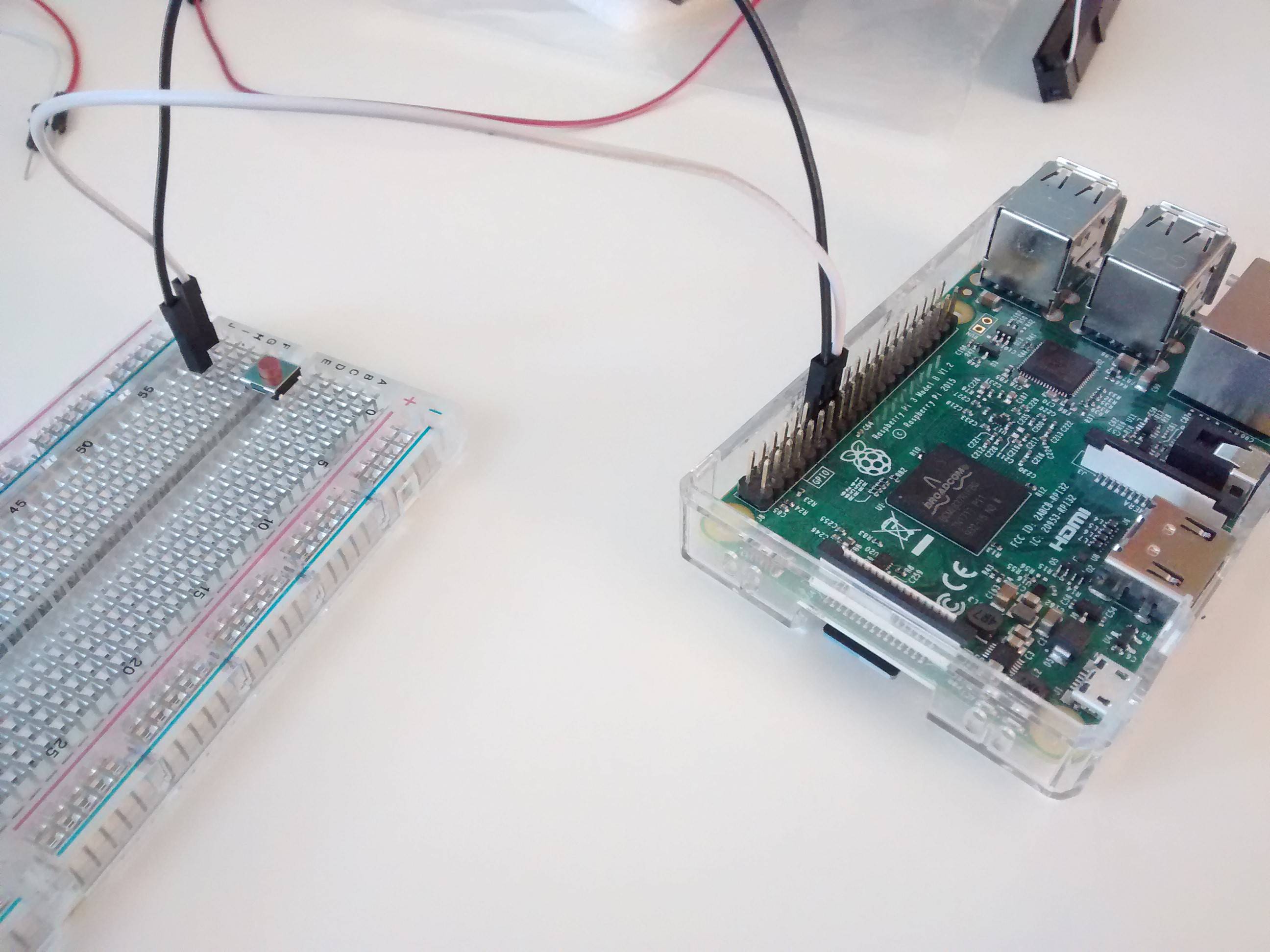
Here is an image of what I've been trying to achieve, which is that when the momentary switch is being pressed, it'll print out "Button Pressed" in Python using a little script.

The problem is that the button is not responding to it being pressed, and the console is either being spammed with "Button pressed" when the value is set to "False", or nothing outputs, not even when the button is pressed, when being set to "True". I've tried moving it from 5 V to 3.3 V and nothing changed.

I'm pretty new to using breadboards and I've been trying to just understand how to use this momentary switch with no success. Any help is appreciated as this has gotten very frustrating by now!

The resistor in the photo is a 10 kΩ 1/4 W resistor:

The resistor in the photo is a 10k Ohm 1/4W resistor

Here's the script I'm using:

import RPi.GPIO as GPIO
import time

GPIO.setmode(GPIO.BCM)

GPIO.setup(23, GPIO.IN, pull_up_down=GPIO.PUD_UP)

while True:
    input_state = GPIO.input(23)
    if input_state == False:
        print('Button Pressed')
        time.sleep(0.2)

UPDATE:

Connected 3.3v to GPIO, switched to GPIO 22 and the same issue happens. I'm starting to think the button's the problem.

3.3v GPIO 22

3
  • somewhat unclear from the photo (black wire, black board and too dark), but the black wire looks like its connected to gpio 24 and not 23 .. could you verify it is not so ? Commented Jul 18, 2018 at 21:40
  • Nope, checked and it was on GPIO 23. Switched it to GPIO 22 and connected 3.3v to the GPIO but the same exact problem happens.
    – user89703
    Commented Jul 19, 2018 at 0:32
  • looking at the button size makes me think it is possible its leads are not long enough to reach the bread board pads to give good contact (meaning its physically there and not electrically part of the circuit). could you check if the resistance changes when you depress/release the button ? alternatively you could try a button with longer leads Commented Jul 19, 2018 at 1:32

3 Answers 3

0

Never connect more than 3.3V to a GPIO. You will likely destroy the GPIO and eventually the Pi.

Are you sure the ribbon cable is connected the right way around. It is a common error to connect them back to front. If you have a meter check that 3.3V and 5V are present at the respective points on the breadboard.

If you connect the two wires connected to the button do you get a reading? If so the button needs to be turned through 90 degrees.

2
  • Turned everything around, switched to GPIO 22 and connected 3.3v to the GPIO, changed the script, the same problem happens, connected to any pins of the button. I'm starting to think the button has a problem. I've switched it with the exact model 2 times, but the same issue arrives. Added a new photo.
    – user89703
    Commented Jul 19, 2018 at 0:35
  • @RaGeX Forget the button. You need to be systematic. Get it working with just a pair of jumper wires connected to the expansion header. Does the GPIO read low when connected to ground. Does it read high when connected to 3V3. Only when that works add the cobbler. Only when that works add the button.
    – joan
    Commented Jul 19, 2018 at 7:50
0

Do you have a separate power supply for the breadboard? If so, please turn it off because you don't need it.

According to the picture, and since you haven't described your circuit with a schematic or words, you might have a classic floating power ground problem!

The other possibility is that the power and ground have been taken from your Raspberry Pi, in which case I apologize.

Would you please measure the voltage between power and ground at the breadboard?

According to the picture, if the button is correctly oriented (verify with a meter!) the gpio should measure low, unless the button is pressed, then it should measure high.

To make this easier to debug, you might want to follow some common conventions. Connections to ground should be black or brown. Connections to signals (the connection to pin 23 in your case) should be yellow or other medium color. The connections to power should be red or orange. If I have multiple voltages, I tend to use red, orange, and white being very specific as to which goes to which voltage. This may seem like nit-picking, but these color conventions make it easier to debug a strange circuit.

0

Alright, after some testing and waiting for packages to arrive, I've finally found out the problem.

So to start, I've got myself a multimeter and checked if 3.3v and 5v were actually present on the breadboard, which they were using the cobbler. Afterwards, I've removed the cobbler completely and used 3 jumper wires and a resistor to check if it was reading low when the GPIO was connected to ground and if it was reading high when connected to 3v3, as joan suggested. It did.
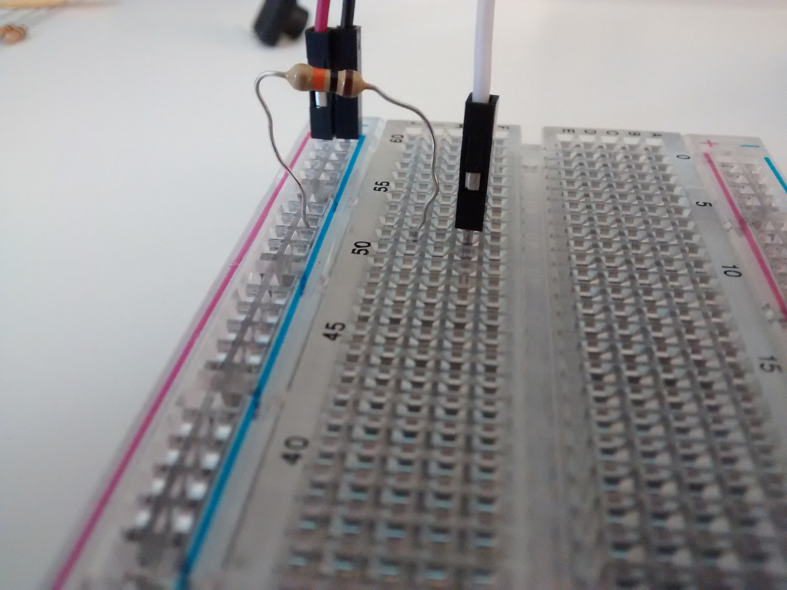
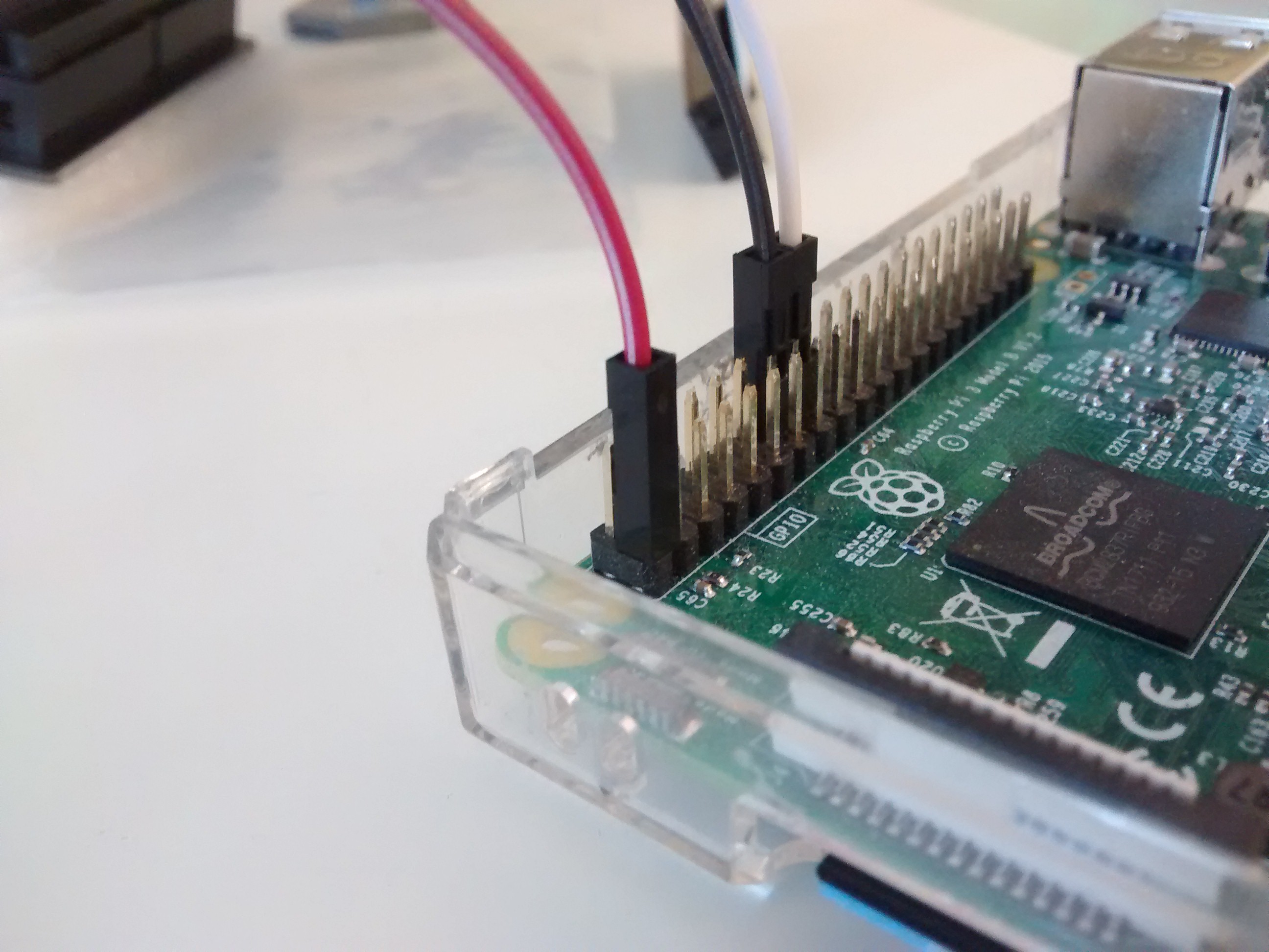
Low pins

As everything was looking fine pretty far, I've decided to add the button and see if the GPIO would measure low when the button was not pressed, and high when it was, as pointed out by NomadMaker.

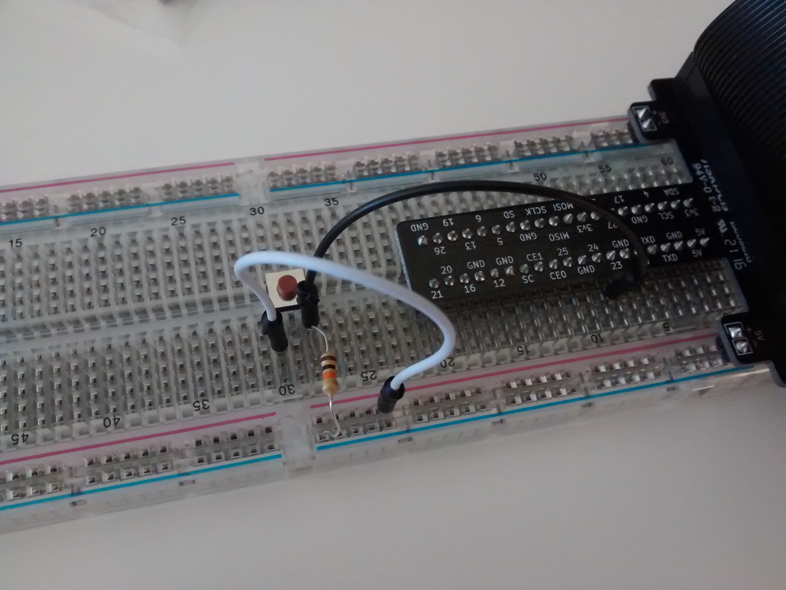
So using the same script, it did measure low when not pressed, but the state did not change when the button was pressed. (It's not possible to rotate the button 90 degrees as it only goes in the correct way).
Unresponsive button

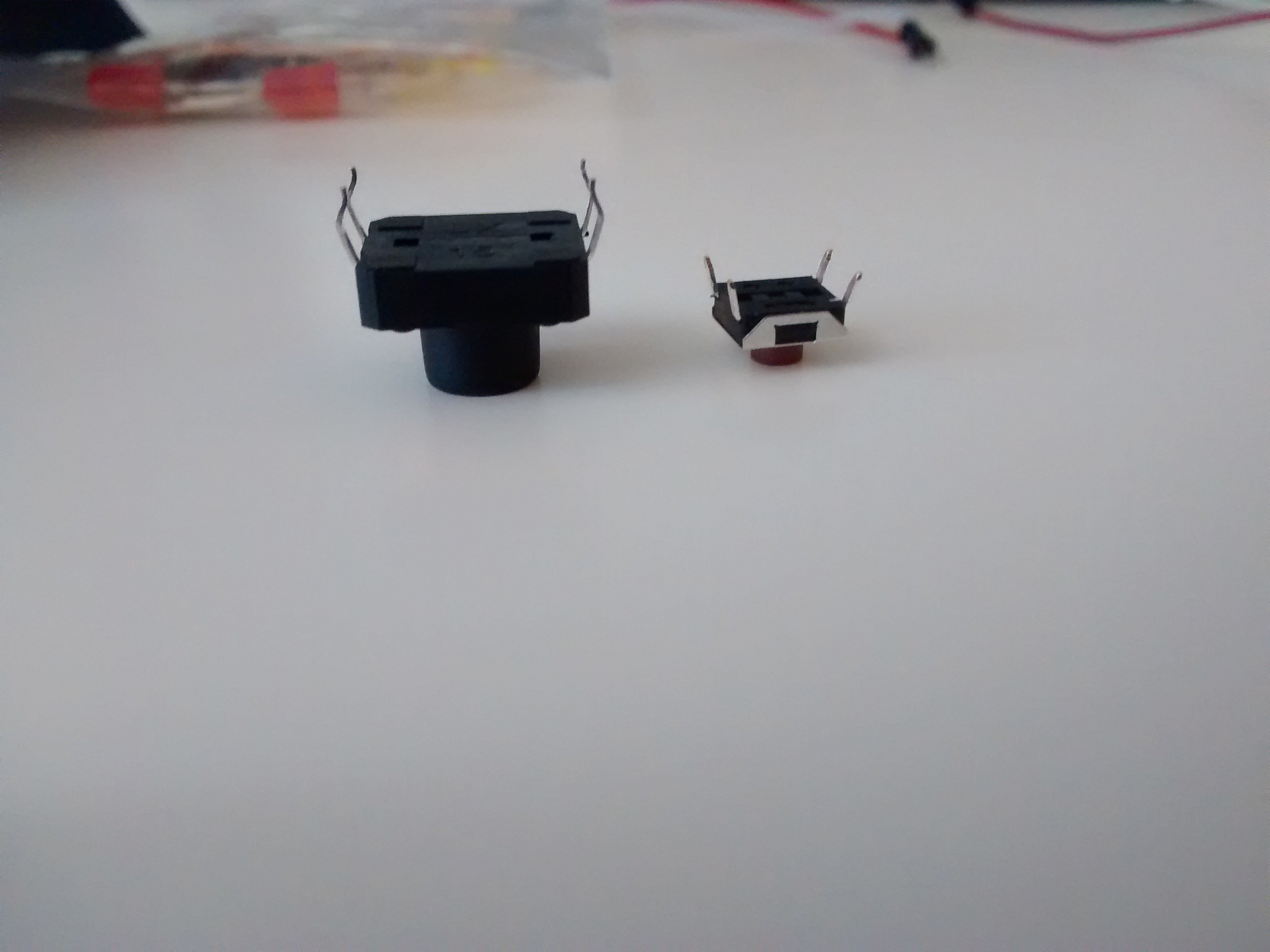
At that point, I was pretty confused. These momentary switches had come from a kit with the breadboard and the pi. In the meantime, I had ordered some bigger buttons to test them out as well, as Shreyas Murali suggested that they may not be making good contact with the breadboard, due to the short leads.

When they've arrived, I've switched (pun not intended) these buttons with the bigger buttons, and right off the bat, I've noticed that the new buttons were way larger and had significantly longer leads than the ones that came with the kit.
Comparison

So, after replacing them, booting up the pi, and running the original script, which would print out the "Button pressed" message whenever the button was pressed, or when the state of the GPIO was high, the result was that... The message was printed. The message was being printed whenever I was pressing the button, as the GPIO state was changing. That's right, the previous buttons were not properly making contact with the breadboard. The momentary switches that came with the kit, were not making contact. It was that simple. What a waste of time! And on top of that, the switches on the cover of the kit are similar to the ones that I had ordered and completely different from the ones you get in the box. Thanks to everyone that tried to help!

TL;DR

The buttons were not making good contact with the breadboard. Anyone having this exact problem with the same switches or the MCM Electronics Project kit, buy your own switches.

Your Answer

By clicking “Post Your Answer”, you agree to our terms of service and acknowledge you have read our privacy policy.