3

I'm designing a HAT and need to supply power to PI zero W and PI 3B+ through the GPIO headers[2&4]. The supply would regulated at 5V 4A (Would be sharing the same power supply with a Thermal printer as well. So 1.5-2 A for pi and 1.5-2 A for thermal printer -- checked). I was following this thread before: That's where I felt the urgency for over current and reverse polarity protection. So decided to make my own simpler protection circuit.

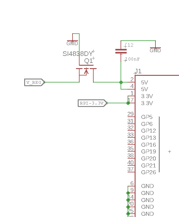
Here's is a schematic. enter image description here

I don't know for sure if this will work before I fry my PIs. Hence asking here for help and support and suggestions.

Do you brilliant folks think this MSOFET circuit is correct and would work? Or do you have better suggestions..

Best Datta

2
  • 1
    Too much current isn't going to fry the pi. Where currents concerned the pi will only use as much as it needs at any one time, you'd have a danger of frying the pi if you went over voltage instead. If your power supply maxes out at 5v you'll be fine as that's what the pi's made for, if it were say 12v you'd fry the pi. As far as the diagrams concerned I'm not great with schematics so wouldn't want to say either way, but as long as your PS is 5v MAX you should be fine.
    – rohtua
    Commented Feb 18, 2019 at 13:54
  • Go it. I would still put a proper regulator. I found this schematic i.sstatic.net/fTD6H.png & i.sstatic.net/eIMHC.png Commented Feb 19, 2019 at 10:47

2 Answers 2

1

The additional complexity (U4) in the pi3 circuit is to ensure the pfet turns on completely, the nominal configuration you have works, but may not be good in all situations. It is worthwhile to put something there , tying gate to ground is only good to "first order" design, the extra stuff is for corner cases which will inevitably come up.

Note that pi zero does not have the same nominal input protection and is pretty "naked" already .

The over voltage diodes present on the PI are not very high power zeners so act as destructive fail safe and intended to suppress inductive spikes not supply deregulation, bigger zeners with current limit would be needed. .

Regulator ics, either library or switch mode are pretty good , unless someone puts the wrong feedback resistor when building the shield I would not worry about it being wonky for your design . If you are selling kits this may be a concern that a user bulds it wrong and fries the pi but if you plan to sell assembled boards I hope you will test to ensure it was assembled right :)

1
  • Thanks. I will take those into consideration Commented Mar 21, 2019 at 5:21
0

The official Foundation HAT guideline has recommended power circuitry.

I suggest you download and study it.

1

Your Answer

By clicking “Post Your Answer”, you agree to our terms of service and acknowledge you have read our privacy policy.

Not the answer you're looking for? Browse other questions tagged or ask your own question.