2

I'm about to build a heating control with DS18B20 1Wire-sensors and the Raspberry Pi 3 Model B+. For the 1Wire-interface I'm using the DS2482-800 multi-channel busmaster (more precisely this pre-assembled board: http://www.sheepwalkelectronics.co.uk/product_info.php?products_id=67).

The sensors are read over OWFS and a Node.js-script (using the owfs-module). I'm using Node.js as the Raspberry is hosting an express-webserver with all the current temperature-values.

Overall this works great, at least for the 11 sensors, which are connected to the first 4 channels of the DS2482. But as soon as I try to connect 2 additional sensors to the 5th channel, these sensors are NOT read by OWFS. Why that?

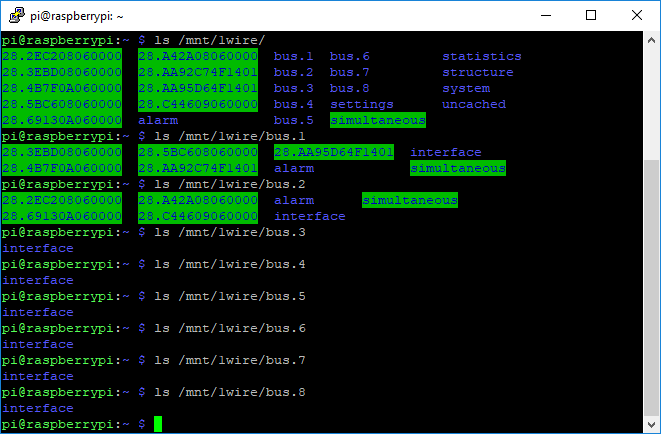
Moreover I noticed, that the virtual /mnt/1wire directory only shows 9 sensors on the first 2 channels, although I'm able to read 11 sensors (on 4 channels) with the Node.js-script without problems. How's that possible???

<code>/mnt/1wire</code> directory shows 9 sensors but with the Node.js-script I'm able to read 11

For test purposes I tried to connect the 2 "new" sensors to one of the first 4 channels -> reading them works perfectly fine, so no issues with the sensors.
Because of that, I think there's a problem with my configuration of OWFS.
My owfs.conf file looks like this:

# Sample configuration file for the OWFS suite for Debian GNU/Linux.
#
#
# This is the main OWFS configuration file. You should read the
# owfs.conf(5) manual page in order to understand the options listed
# here.

######################## SOURCES ########################
#
# With this setup, any client (but owserver) uses owserver on the
# local machine...
! server: server = localhost:4304
#
# ...and owserver uses the real hardware, by default fake devices
# This part must be changed on real installation
# server: FAKE = DS18S20,DS2405
#
# USB device: DS9490
#server: usb = all

server: device = /dev/i2c-1

# Serial port: DS9097
#server: device = /dev/ttyS1
#
# owserver tcp address
#server: server = 192.168.10.1:3131
#
# random simulated device
#server: FAKE = DS18S20,DS2405

######################### OWFS ##########################
#
mountpoint = /mnt/1wire
allow_other
#
####################### OWHTTPD #########################

!http: port = 2121

####################### OWFTPD ##########################

ftp: port = 2120

####################### OWSERVER ########################

server: port = 4304

I really appreciate your support, as I couldn't find anything helpful via Google and I'm preety stumped right now...

Thanks in advance

10
  • I read the datasheet and found that your "bus master" is (1) a "8 Channel I2C to 1-Wire host adapter, and (2) this module uses a DS2482-800 IC to provide 8 separate 1-Wire channels. So I guess it is sort of "1-Wire channel multiplier". Please correct me if I am wrong. Now I guess you wish each of the 8 1-Wire channels to handle as many 1-Wire sensors, ie DS18B20 as possible. I had the same problem as yours. Let me se if I can find my old answer to refresh my memory. See you later.
    – tlfong01
    Commented Apr 16, 2020 at 12:42
  • Now that I found my old answer: "DS18B20 Temperature Sensor - Rpi 3/4 Driver, Wiring, Detection, and Python Programming - Asked 9 months ago Viewed 763 times": raspberrypi.stackexchange.com/questions/100203/…. Now I remember that one Rpi GPIO pin can handle at least 12 DS18B12 sensors. In other words if you want to entertain, say 64 sensors, you need 5 GPIO pins.
    – tlfong01
    Commented Apr 16, 2020 at 12:50
  • 1
    Thanks for your quick answer. But you are referring to an arrangement, where the DS18B20 sensors are connected directly to the RPi GPIOs, which is NOT the case in my installation. I'm using the DS2482-800 busmaster, which comunicates with the RPi only through I2C, no other GPIOs used (it's no multiplier, but provides "8 Channels of Independently Operated" see datasheet datasheets.maximintegrated.com/en/ds/DS2482-800.pdf )
    – simsnWolke
    Commented Apr 16, 2020 at 13:29
  • Hi @simsnWolke, yes, I agree I am not answering your question directly, but just brainstorming that you might forget the bus expander/mux/demux/ (OK, not "multiplier") and just use GPIO instead. I am aware that GPIO wires cannot go far, so one workaround is to use I2C, plus I2C extenders and expanders, otherwise I2C alone, even at 100kHz, cannot go reliably further than a couple of meters, before hitting the 400pF impedance limit. I remember when I tested the max number of 1-wire sensor per GIPO, I read Maxim's literature about how to do long distance sensing, using / to continue, ...
    – tlfong01
    Commented Apr 16, 2020 at 14:18
  • their purposely designed extenders. Let me see if I can find Maxim's app notes, to refresh my memory, and compare your "expander" then come back to you. Cheers.
    – tlfong01
    Commented Apr 16, 2020 at 14:21

2 Answers 2

0

Question

DS2482 I2C to 1-Wire module using python OWFS (One Wire File System) cannot detect all the connected DS18B20 temperature sensor devices. How to fix the problem?

ds2482 modules


Answer

Suggestions:

(1) Enable the DS2482's SPU (Strong Pull Up) MOSFET (Appendix G),

(2) Lower 1-Wire speed.

(3) Remove the two I2C pullups connected to the DS2482 module (Appendix D).

/ to continue, ...


Part 1

Configuring python owfs (Refs 29, 32)
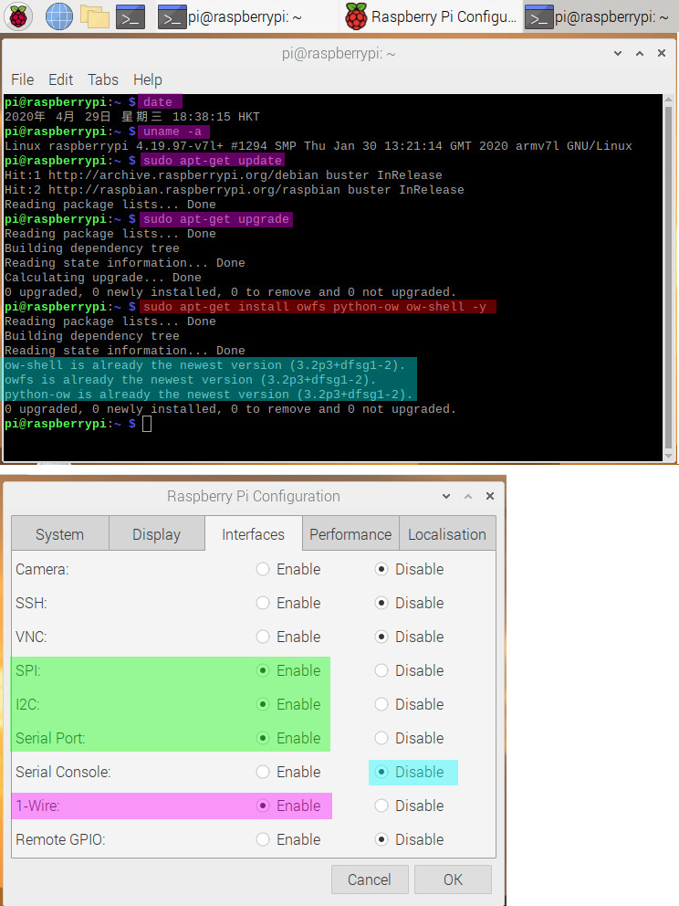
owfs install config


Part 2 - Testing OWFS Server without any DS18B20 sensor connected.
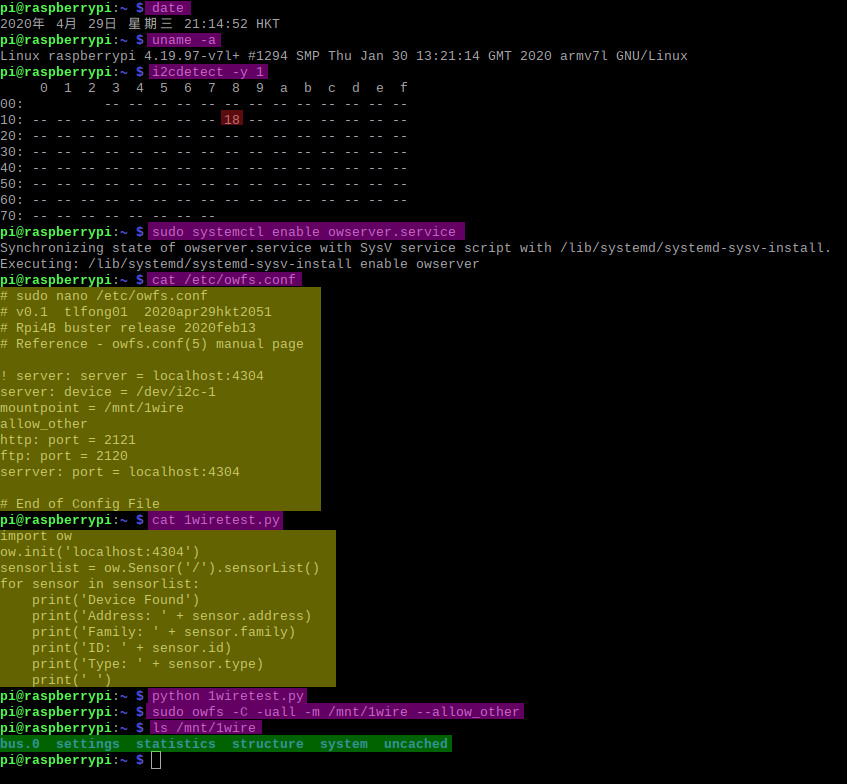
owfs server test


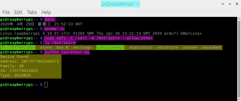
Part 3 - Detecting One DS18B20 Temperature Sensor
ds18b20 test


Part 4 - Soldering second DS2482-100 chip to breakout board for testing.

Soldering the chip to the breakout board took me 7 minutes. The pins are 0.05" apart. So it is not that difficult to complete the soldering task. My trick is the following: (1) Separately tin only one pin and one pad, (2) Put the chip on top of breakout board and use the soldering tip to melt the only one pin to pad, with a couple of trial and errors to precisely position the chip. The duPoint male connector pin soldering job are easy. Final multi-meter open short testing is also straighforward.

ds2482 soldering


Part 5 Testing two DS2482 and twoDS18B20 sensors

Reference - (37) Rpi 1-Wire Tutorial - Packt 2015

This tutorial by Packt is the most helpful one for newbies. Packet gives a good introduction on the general 1-Wire concepts and then use AB Electronics' DS2482-100 board as the example on setting up and testing the sensors. Unfortunately the illustration images are not readable, so I need to make guesses.

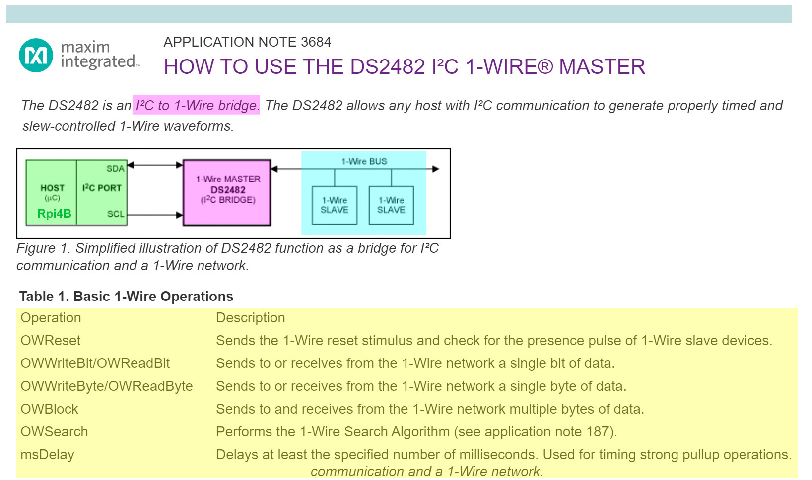
The testing procedure is a bit tricky, so I am making a summary of the steps below.
ds2482 op

/ to continue, ...


References

(1) DS18B20 Temperature Sensor Setup and Programming Q&A

(2) Rpi4B buster I2C Speed Test 6.0 - tlfong01 2020mar04

(3) DS2482-100 1-Channel 1-Wire Master Datasheet - Maxim

(4) DS2482-800 8-Channel 1-Wire Master - Maxim

(5) AK-DS2482S-100 – 1-Channel 1-Wire Master Breakout Product Sheet - Artekit

(6) AK-DS2482S-100 – 1-Channel 1-Wire Master Breakout Schematic - Artekit

(7) AK-DS2482S-100 – 1-Channel 1-Wire Master Breakout User Manual - Artekit

(8) DS2482-800 8-Channel 1-Wire Master Module - SheepWalk

(9) OWFS 1-Wire File System - OWFS

(10) OWFS and OWHTTPD Project Docs - SourceForge

(11) How to enable DS2482 SPU - Ivan2 Artekit Product Comments 2018

(12) OWFS Node.js Client Library For 1-Wire Devices Using OwServer Protocol

(13) Application Note 3684 How to Use the DS2482 I2C 1-Wire Master - Maxim

(14) Kernel driver ds2482 Supported chips Maxim DS2482-100, Maxim DS2482-800

(15) Interface Driver for Maxim DS2482 1Wire-to-I2C bridge IC - Stefan Guenther

(16) OWFS Manual Page (I2C DS2482-100, DS2482-101 and DS2482-800)

(17) OWFS with i2c support on Raspberry Pi (English version)

(18) OW version 2.0p0RC-1.6

(19) Python OW Server Discussion

(20) 1 Wire with DS18S20 digital thermometer (Bash) - ABelectronis 02/02/2019

(21) DS2482-100 1-Wire to I2C host interface - ABelectronics

(22) OWFS with I2C support on Raspberry Pi (Python) - ABelectronics 2019mar09

(23) DS2482 Kernel driver for Maxim DS2482-100, Maxim DS2482-800

(24) DS2482 Kernal Driver - Stefan Guenther

(25) DS2482 Driver - torvalds

(26) Linux Kernel driver DS2482 for Maxim DS2482-100, Maxim DS2482-800

(27) Introduction to the 1-wire (w1) subsystem

(28) The Linux Kernel documentation 5.7.0-rc

(29) OWFS with I2C support on Raspberry Pi (for stretch) Tutorial - AB Electronics 2015

(30) OWFS with i2c support on Raspberry Pi - Wiki.m.nu

(31) OW (version 2.0p0RC-1.6)

(32) Rpi Python 1-Wire File System to read DS2482 I2C to 1-Wire bridge connected DS18B20 Temperature Sensors

(33) Kernel Driver DS2482 - Linux Kernel.Org

(34) How to build and use the kernel of the Rpi I2C to 1-Wire Bridge DS2482? - 2020

(35) How to use the DS2482 kernel module? - 2018

(36) Rpi Python 1-Wire File System to read DS2482 I2C to 1-Wire bridge connected DS18B20 Temperature Sensors (same as Ref 32, problem solved)

(37) Rpi 1-Wire Tutorial - Packt 2015

(38) RJ12 Plug and Cables - AB Electronics

(39) DS2482 Board Schematic - AB Electronics

(40) DS9503 ESD Protection Diode with Resistors - Maxim


Appendices

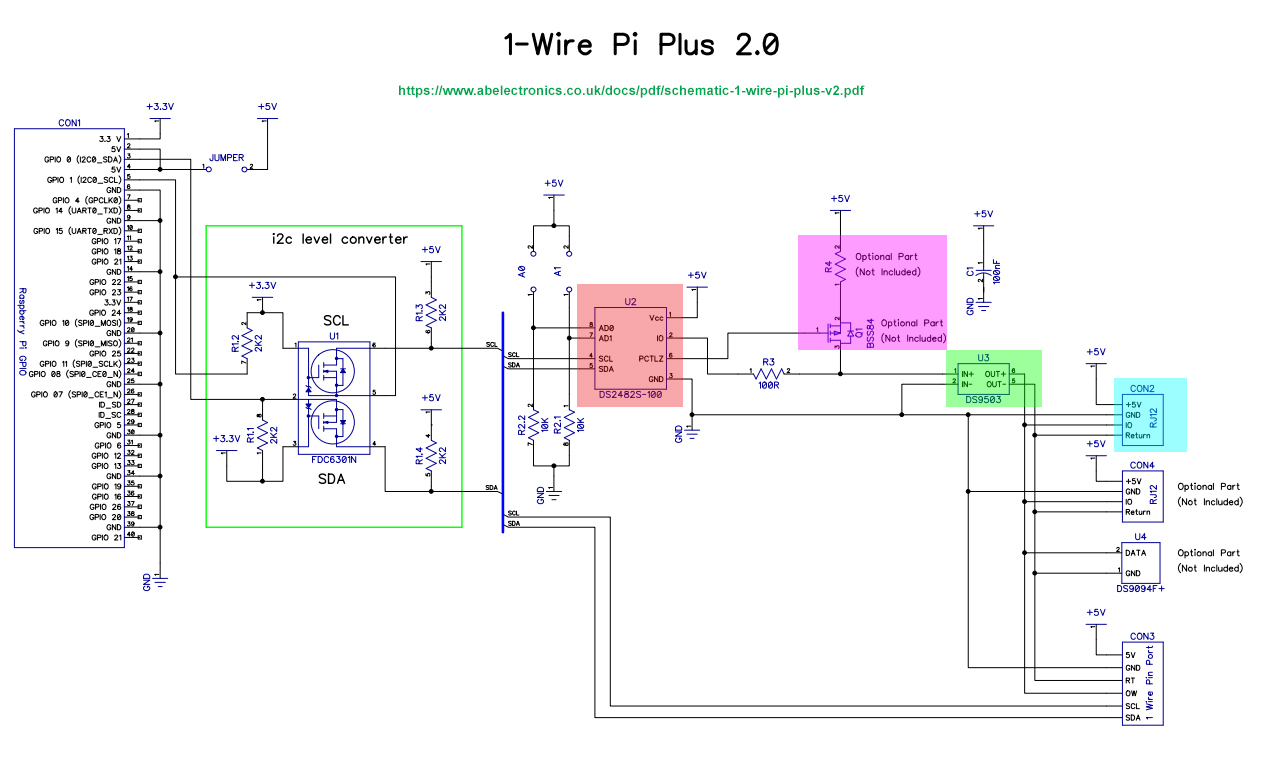
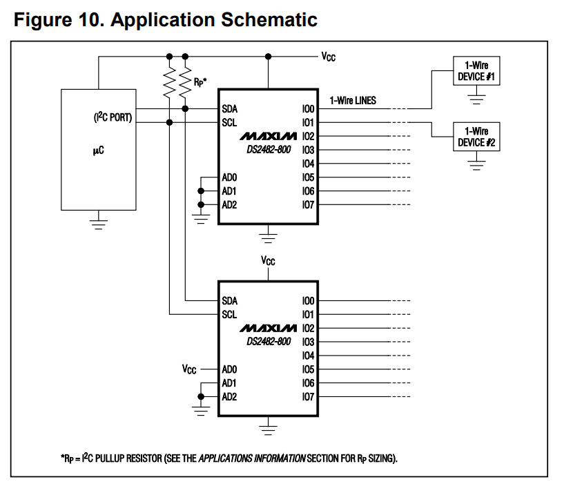
Appendix A - DS2482-800 Application Schematic
ds2820 app sch

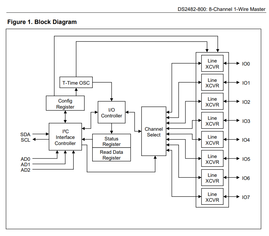
Appendix B - DS2482-800 Block Diagram
ds2482 block


Appendix C - DS2482-x00 Modules

ds2482 modules


Appendix D - DS2482-100 Schematic and Block Diagram
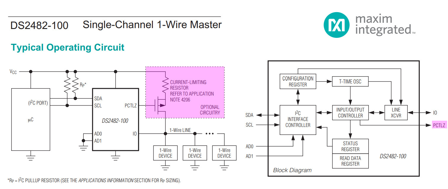
ds2482-100 schematic and block diagram


Appendix E - Enabling SPU (Strong Pull Up) of the DS2482 1-Wire Host Module

Application Note 3684 How to Use the DS2482 I2C 1-Wire Master - Maxim

How to enable DS2482 SPU - Ivan2 Artekit Product Comments 2018

The SPU pad is for the strong pull-up, to be used with the PCTLZ pin to control the on-board MOSFET. Both APU (active pull-up) and SPU (strong pull-up) must be activated using the internal registers. - Ivan2

App Note 3684 describes how to use the internal registers to (1) enalbe SKU, (2) change 1-Wire speed. One easy way to access the DS2482 registers is to use python I2C functions - tlfong01


Appendix F - Testing DS2482-100 using Linux kernel drivers

I googled and found a couple of kernel drivers for DS2482-100/800. I found the following Linux driver has the most comprehensive documentation, and therefore should be most friendly to newbies like me.

(26) Linux Kernel driver DS2482 for Maxim DS2482-100, Maxim DS2482-800

(27) Introduction to the 1-wire (w1) subsystem

(28) The Linux Kernel documentation 5.7.0-rc


Appendix G - DS2482-100 Schematic
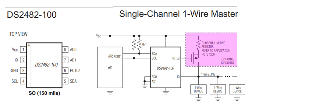
ds2482

ab enc ds2482 schematic

1
  • Comments are not for extended discussion; this conversation has been moved to chat.
    – goldilocks
    Commented Apr 26, 2020 at 18:21
0

Sorry for the very very late answer now, but somehow I needed to get some distance from that project to clear my mind during the last few months.
@tlfong01 A big Thank you for your very detailed explanations and for the amount of effort you put in answering my question, I appreciate it very much.

But I took a bit of an other approach for solving my problem:
By searching the web, I came across these 1Wire-USB-Interface: iButtonLink LinkUSB™
It claimes to be much more reliable than other 1Wire-Interfaces as

It has a special analog interface designed to match impedances and slew rate controls, and smart cable pre-charge.

So I ordered two of these and connected some of the longer distance DS18B20-sensors to them (the sensors with shorter cable-distances are still attached to the DS2482-800). And indeed: Without any additional modifications the 1Wire-bus worked far more reliable. So I can definitely recommend such USB-Interfaces to anyone, who has troubles with building a stable 1Wire-network.

But even though this was a big step in the right direction, the bus still crashed once or twice a day and didn't recover until the raspberry was rebootet (or the LinkUSBs were unplugged for a few seconds). So I looked for a way to cut the USB-power-supply of the LinkUSB over software in order to "reset" the 1Wire-Interface. This could be achieved with libusb-dev and the hub-ctrl-command.

Conclusion: Now everytime the reading of the temperature-values fails continuously within a longer period of time the usb-power gets cut for a few seconds before the 1Wire-bus gets read again. With this "dirty" workaround I finally managed to get pretty stable 1Wire-readouts. The system is running for 2 month now without any incidences.

I KNOW:
Technically speaken this IS NOT a scientific answer to my initial question, it is more a workaround for a workaround. But nevertheless I wanted to share my solution with you guys, maybe it can be helpful for someone out there in some way.

Your Answer

By clicking “Post Your Answer”, you agree to our terms of service and acknowledge you have read our privacy policy.

Not the answer you're looking for? Browse other questions tagged or ask your own question.