4

I connected an RGB LED(common anode) via the GPIO, and tried to get it to light up, but for some reason when I run the command, the LED does not light up. Here's the code I'm using

import RPi.GPIO as GPIO

GPIO.setmode(GPIO.BOARD)

GPIO.setup(11, GPIO.OUT)
GPIO.output(11,1)
GPIO.setup(13, GPIO.OUT)
GPIO.output(13,1)
GPIO.setup(15, GPIO.OUT)
GPIO.output(15,1)

try:
    while(True):
        request = raw_input("RGB:")
        if(len(request) == 3):
            GPIO.output(11, int(request[0]))
            GPIO.output(13, int(request[1]))
            GPIO.output(15, int(request[2]))
except KeyboardInterrupt:
    GPIO.cleanup()

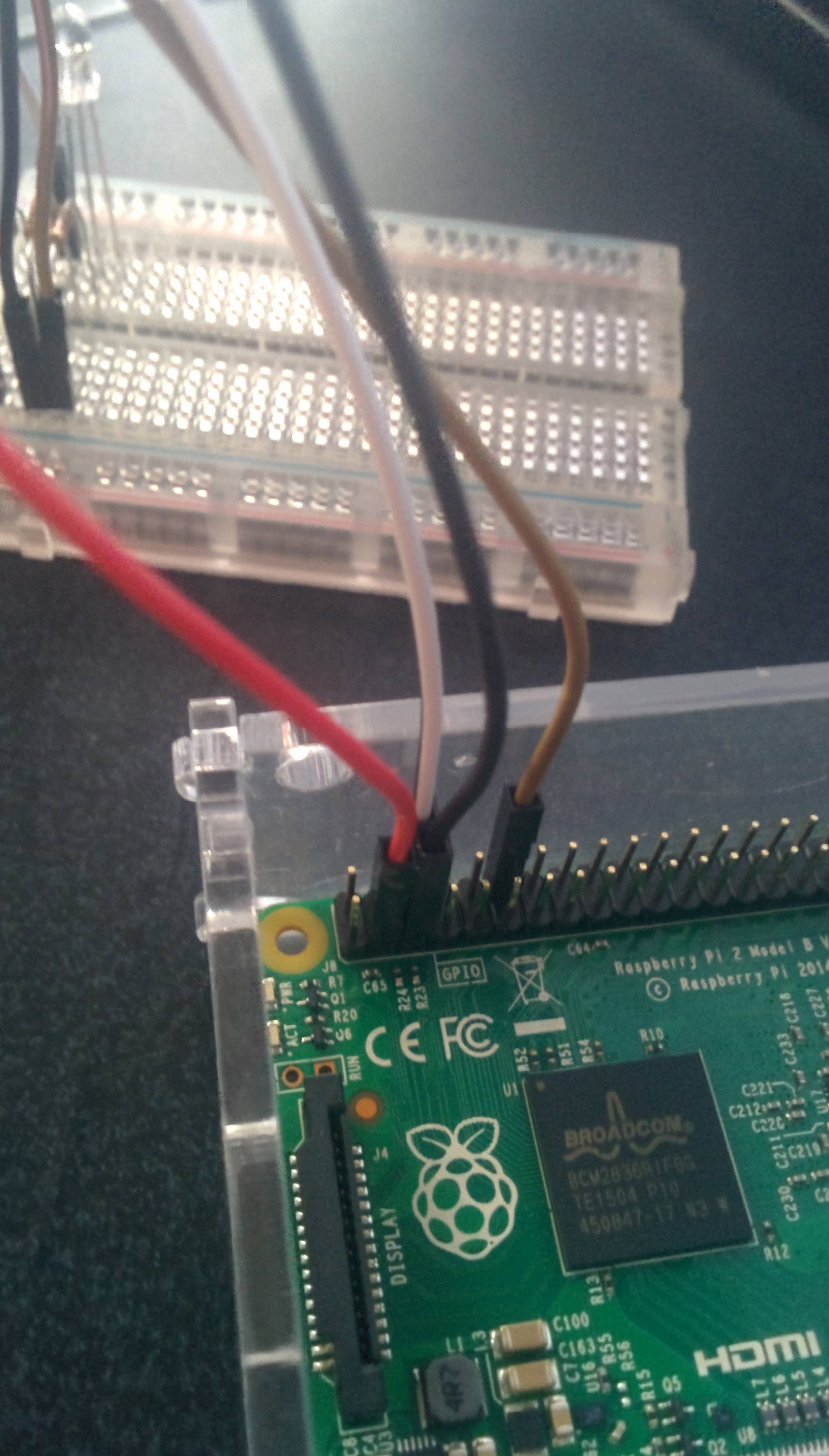
And this is what my setup looks like enter image description here enter image description here
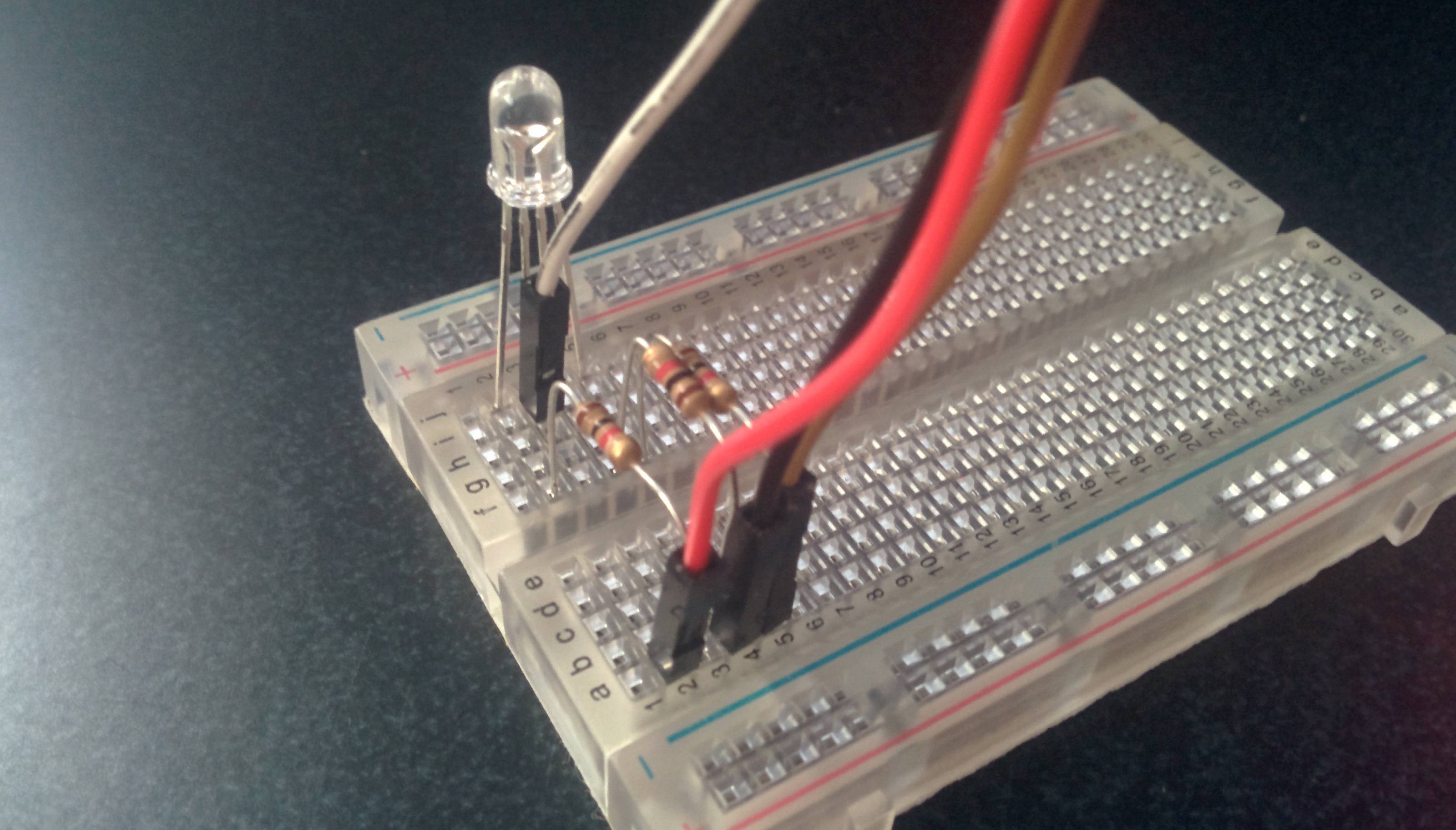
Any ideas what I'm doing wrong? It's my first week working with my Raspberry Pi.

6
  • 1
    If the RGB is common anode doesn't that mean the individual legs need to be low for on and high for off? I.e. have you connected the common anode to the 3V3 rail? You don't appear to be using pins 11, 13, or 15, yet your code is referencing them.
    – joan
    Commented Apr 23, 2015 at 21:03
  • @joan I see, so I set them to 2,3, and 18. But when I go to run the code, I get GPIO.setup(2, GPIO.OUT) ValueError: The channel sent is invalid on a Raspberry Pi
    – Idris
    Commented Apr 23, 2015 at 21:08
  • Is it just me or does it look like you have the common pin anode connected to the ground pin on the pi? Commented Apr 23, 2015 at 21:11
  • Yeah that's what I did, was I not supposed to do that? @SteveRobillard
    – Idris
    Commented Apr 23, 2015 at 21:12
  • Not if the LED is common anode. anode = they share common power cathode = shared ground. As Joan said with a common anode LED the individual colors are turned on by pulling the pin they are connected to low. Commented Apr 23, 2015 at 21:14

1 Answer 1

3

A common anode LED should have the common leg connected to 3.3 volts and the others connected to 3 seperate GPIO pins. Connect the common pin to 3.3v, then wire the other three legs of the LED to the desired GPIO pins. In your code pull these pins low to light the individual colors. The resistors should go between the LED color pins and the GPIO pins.

Here is a quick check connect the common pin and one color pin with a resistor and wire the common pin to 3.3v and the other to the Pi's ground pin. If you have the polarity right it should light one color. if it does not light switch the ground and 3.3v wires.

Once you are sure the polarity is correct connect your chosen GPIO pins to the LED's other three legs (non common), including current limiting resistors.

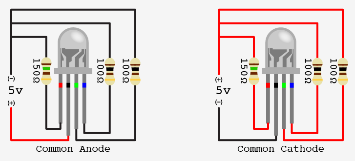
The voltage and specific resistor values don't apply assuming you are using the 3.3v pin to power your LED, but the image below should make clear the difference between common anode and cathode, and how to wire them. Note that the picture shows the three color legs connected to a single pin, but you need to use three pins to control all three colors.

enter image description here

2
  • Just did the check, and it works! So now to get the full RGB feature, I'd connect the remaining two to any GPIO, or all 3 to the GPIO, and leave one at the 3.3v?
    – Idris
    Commented Apr 23, 2015 at 21:23
  • @Idris Yeah connect all three of the pins (leaving the common pin connected to the 3.3v pin on the PI) to a GPIO pin that you pull low in your code. Is that clear? Commented Apr 23, 2015 at 21:47

Your Answer

By clicking “Post Your Answer”, you agree to our terms of service and acknowledge you have read our privacy policy.

Not the answer you're looking for? Browse other questions tagged or ask your own question.