1

I need your's help with dimmer which is controlled by Raspberry PWM. My problem is lack of synchronization PWM with power supply. Unfortunately , I don't have oscilloscope waveforms to show my problem, but I can show my python script and electrical drawings which I use.

Firstly: Electrical drawings.

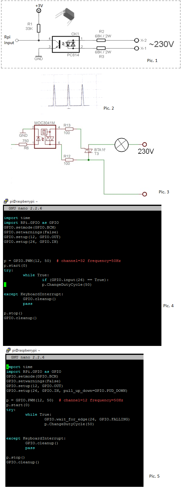
Picture 1 presents zero-cross detection circuit R1 - 33K , R2 and R3 - 68K and optocoupler PC814. This give me high signal in Raspberry input, when power supply is equal 0 and I obtain waveforms like in Pic. 2

MOC 3021 and BTA16 triac I use to dimming my light bulb. In Pic. 3 is shown MOC3041, but I use MOC 3021.

Secondly: Pyhton script.

Pic. 4 - This is one of my python scripts. I use simple commands ( don't look at comment :) ). When input is high then will be run PWM with duty cycle 50. And second script in Pic. 5 - I use in this interrupts. I used interrupts with falling and rising edge.

So, when I run my script (Pic. 4 or Pic. 5) my PWM signal doesn't have synchronization with 230V power supply. PWM isn't triggered when it should. I'm angry that I didn't do oscilloscope waveforms. I think that hardware is good but software is bad. I supported with another project where somebody used those elements (MOC 3021 and PC814) and it worked fine, but used ATmega32.

Thanks for help ! :)

enter image description here

3
  • It's a bit hard to comment as you have not said what you are trying to do. What do you intend to happen when a zero crossing is detected?
    – joan
    Commented Nov 28, 2015 at 22:44
  • @Joan - I was going to say this falls out of the statement of the problem as a dimmer, though now that you make me look at it again part of the problem is that the software seems to be written without a clear understanding of what should be happening in response to zero crossing. Commented Nov 28, 2015 at 23:19
  • @ChrisStratton I know that something needs to be done when the zero crossing is detected, I just don't know what. It's often the case that we get details of a supposed solution to a problem whereas if we got better details of the problem we might know a more correct solution.
    – joan
    Commented Nov 28, 2015 at 23:24

2 Answers 2

2

Generally speaking, this is a task for a small barebones embedded MCU (like the referenced ATmega), not something running a multitasking operating system like a pi typically does - the pi is not only drastic overkill for the task, makes overcoming interrupt latency a challenge, it is also the type of exposed platform with galvanic connections which one must be exceedingly careful of when working in the proximity of line voltages, even when optoisolation is theoretically employed.

Further, MCU-based TRIAC dimming is the type of problem with general details which really belong far more on EESE, rather than on a pi-specific site.

However, to address a very specific problem in your design, your apparent attempt to use PWM with 50 Hz frame timing generated by the pi is inconsistent with how a TRIAC dimmer works.

TRAICs are essentially one-way-controllable switches - they can be turned "on", but not "off". However, they are useful for AC circuits, because they will automatically turn-off when the current falls below a hold-value at zero crossing. As a result, you can achieve a pulse-width type of modulation with a TRIAC, by waiting some time after zero crossing to turn the TRIAC on, and then having it be on for only the remaining part of the cycle until the next zero crossing.

To do this, you would not use a PWM configuration, rather you would implement a programmable delay from the interrupt indicating zero crossing, until the output driving the TRIAC. In some MCUs with versatile counter timer blocks, you might be able to do this using mechanism somewhat resembling those used for PWM, but still fundamentally different as the "framing" of the waveform comes from the AC line, and only the delay producing the duty cycle comes from the counter-timer.

When I prototyped a similar system recently, I had the Linux-based user-interface, talk over I2C to an MCU (ATmega in the prototype, TBD pending cost analysis for production) which did the actual tight-timing zero crossing and TRIAC activation delay, along with closing a loop based on measurements of what the TRIAC is actually controlling. That permitted clean segmentation of the software and removed latency concerns of the Linux scheduler from the actual TRIAC control function. It also meant that the application-specific powerline electronics could be contained on an inexpensive and easily revised 1- or 2- layer PCB, while the far more costly to develop Linux processor board could remain task-agnostic.

1

Well done on including the bare bones of the circuitry you are trying to use!

As @Chris has said your use of the Triac is not correct in that it does not conduct electricity through the main terminals (MT1 <==> MT2 or in this case pins 4 and 6) until a sufficient gate pulse is delivered into the gate terminal - or, in this case, as you have very wisely opted to use a optically isolated one, until a sufficient pulse of current is sent through the LED. It will continue to conduct until the current through it falls to a low enough value that it switches off - this is the simplistic case when the load is mainly resistive but any significant capacitance or inductance will mess with this (i.e. it will a good model for an incandescent light bulb but considerably less so for a motor).

For starters though your zero detection circuit will not be producing the signal you expect - the LED in the PC814 will be illuminated for virtually all of one half of a mains cycle, that means the photo-transistor will be conducting and thus pull the pin going to the Raspberry Pi to around VCE(sat) above 0 volts which will be around 0.4 or 0.5 volts I expect. For the rest of the time the input to the Pi will be pulled up via the 33K; to get a pulse around the time of both zero-crossings (i.e. at a 100hz rate) you'll need to feed the PC814 LED via a bridge-rectifier circuit - without a smoothing capacitor. Um, I looked at a datasheet for this device and found that both those diode devices are optical emitters i.e. LEDs, the one further from the transistor symbol is not a reverse polarity protection device as I at first thought! That being said the waveform you show as Pic2 is inverted - the transistor will be turned on and saturated for virtually all the cycle (one of the LEDs is illuminated except for a very small time around the zero-crossing) and thus the pin to the Pi will be low except for a very small time around the zero-crossing. Also the 33KΩ and 3.3 volt supply mean the peak Ic for the transistor is 0.1mA which is off the range that is characterised in the datasheet I saw, given the capabilities of the Pi's 3.3V supply I'd drop that resistor to, say 6.8KΩ to raise the current to nearly 0.5mA which just about gets it onto the ranges shown on the graphs in the datasheet.

To get a controllable power output you must start a timer as soon as you detect a zero crossing with a minimum of around half the width of the pulse (so that ideally you start the timer at the peak of the pulse which neglecting the turn-off time of the photo-transistor in PC814 is the point when the current though the load is passing through zero) and a maximum of a bit less than the half-cycle time (10 mSec for 50Hz mains) less the time you allowed at the start and the time you need for the pulse to turn the output TRIAC on - then when the timer has ended THEN you send that pulse to turn the output on for the time to the end of THAT half-cycle. The longer the delay before sending that pulse the less the power that gets put into the load.

You will want to tweak those timings (minimum, maximum and turn-on pulse duration). As for the quality of the timing overall, we are talking a timer being run every 10 milli-Seconds but which does need a fairly low latency to detect the start time to be initiated by the zero-crossing detection; I do not know how good the Pi can be made to respond to the signal, ideally it would be an interrupt input which is not something I had have exposure to on the Pi series.

MAINS ELECTRICITY IS DANGEROUS! - The use of (optical) isolation is vital in this usage case, I'd strongly urge you to put all of the circuitry you have shown on a separate PWB in a separate enclosure (which needs a tool to open it), with at least a 6mm gap between every copper track (and the pads thereon) on the live side and the low-voltage stuff which the Opto devices will straddle. Also a suitably rated fast blow fuse in the Live supply rail before the feed to the Opto-isolator PC814 and to wire the Opto-Triac between the Live supply and the load (so that if the TRIAC fails open-circuit the load is not left pulled up to the Live supply) - though the failure mechanism for TRIACs does seem to be to fail short-circuit in my experience! Remember also to fasten the wiring on both sides of the "Mains Barrier" especially on the Live side so that there is more than one thing holding each wire (as short as possible and not possible to cross the barrier unless with TWO layers of insulation a.k.a. DOUBLE-insulated) in place (a two screw per terminal block OR solder and a tie wrap to the PWB for each conductor) and a Mains Warning label on the outside of the enclosure, etc., etc. ...

Disclaimer: The above constitutes advice only, I accept no liability for anyone taking it and would urge everyone who plans to do something like this to satisfy themselves that they are aware of the risks and responsibilities for them and un-informed others who may come into contact with what they have done.

{FTR: I hold a BEng(Hons) in Electrical & Electronic Engineering}

Your Answer

By clicking “Post Your Answer”, you agree to our terms of service and acknowledge you have read our privacy policy.

Not the answer you're looking for? Browse other questions tagged or ask your own question.