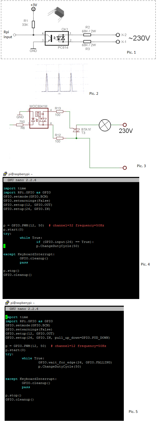
I need your's help with dimmer which is controlled by Raspberry PWM. My problem is lack of synchronization PWM with power supply. Unfortunately , I don't have oscilloscope waveforms to show my problem, but I can show my python script and electrical drawings which I use.
Firstly: Electrical drawings.
Picture 1 presents zero-cross detection circuit R1 - 33K , R2 and R3 - 68K and optocoupler PC814. This give me high signal in Raspberry input, when power supply is equal 0 and I obtain waveforms like in Pic. 2
MOC 3021 and BTA16 triac I use to dimming my light bulb. In Pic. 3 is shown MOC3041, but I use MOC 3021.
Secondly: Pyhton script.
Pic. 4 - This is one of my python scripts. I use simple commands ( don't look at comment :) ). When input is high then will be run PWM with duty cycle 50. And second script in Pic. 5 - I use in this interrupts. I used interrupts with falling and rising edge.
So, when I run my script (Pic. 4 or Pic. 5) my PWM signal doesn't have synchronization with 230V power supply. PWM isn't triggered when it should. I'm angry that I didn't do oscilloscope waveforms. I think that hardware is good but software is bad. I supported with another project where somebody used those elements (MOC 3021 and PC814) and it worked fine, but used ATmega32.
Thanks for help ! :)

