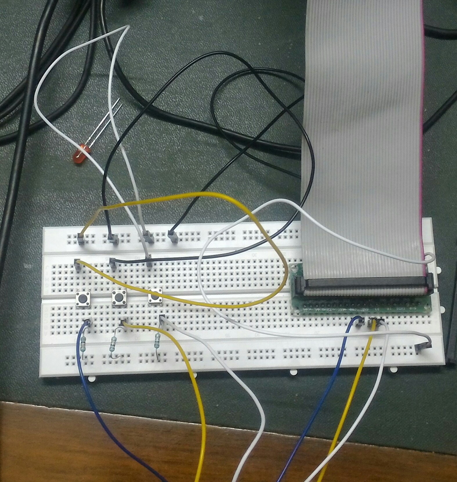
I am new to Raspberry PI. I am following button tutorial from adafruit site.
I have the made the connection needed but when I execute the code the following part is not returning values as expected
GPIO.input(23)
GPIO.input(24)
GPIO.input(25)
it is always returning false resulting in MP3 being played continuously.
I have double checked my circuit and it is as per the diagram shown.
Update:
I was able to get it to work by changing the code to setup the pins.
#!/usr/bin/env python

import os
from time import sleep

import RPi.GPIO as GPIO

GPIO.setmode(GPIO.BCM)
GPIO.setup(23, GPIO.IN, pull_up_down = GPIO.PUD_UP)#added pull_up_down
GPIO.setup(24, GPIO.IN, pull_up_down = GPIO.PUD_UP)#added pull_up_down
GPIO.setup(25, GPIO.IN, pull_up_down = GPIO.PUD_UP)#added pull_up_down

while True:
    if (GPIO.input(23) == False):
        os.system('mpg123 -q Dontfail.mp3 &')


    if (GPIO.input(24) == False):
        os.system('mpg123 -q Failedme.mp3 &')


    if (GPIO.input(25)== False):
        os.system('mpg123 -q Vadrbrth.mp3 &')

    sleep(0.1)
My question now is how come in the video the unedited program was working ? Has something changed in the new version of the Raspberry PI ?
Here is the photo of the circuit

The rail at the top is connected with ground and the bottom is connected with 3.3v. The resistor is of 10k Ohm.
Update 2:
I did some digging into the code for setup and following were my observations:
If the pull_up_down parameter is not passed to the setup function it is assigned as PUD_OFF by default.
When the pull_up_downis PUD_OFF the process of setting pull up down function executes a different code which I am not able to understand now.
But by passing the value as PUD_UP the code necessary for setting it for using pull up resistor is used and it works as intended.
Any explanation regarding what is happening in this function is welcome.
