0

Now I'm still rather new to this but bare with me here-

I wish to emulate a 1-wire bus using my raspberry pi so that I can read/write data on a DS2431 EEPROM chip. So far I believe that I've been able to configure a gpio pin to enable the 1-wire interface with some editing to the config file but this is where I hit a wall.

It appears that some drivers exist for the chip under kernel/drivers/w1/slaves/w1_ds2431 however I'm not sure how to implement these files. I can't seem to find much information on interfacing with the chip even though it seems to be supported.

Any advice or helpful links that could make this process easier for me? Thanks in advance.

2
  • Take a look at 1-Wire Public Domain Kit.
    – hcheung
    Commented May 25, 2017 at 1:25
  • Thanks that's closer to what I'm looking for but those links don't seem to pertain enough to interfacing with an RPi.
    – Devos
    Commented May 25, 2017 at 19:12

1 Answer 1

3

I know it's old question but just in case someone will look for it in the future, here's how I made it to work:

First the wiring, datasheet on Maxim is misleading at least for me. So looking straight at the FLAT side of the EEPROM, going from left to right you have: GND, IO, NC.

  1. Connect GND pin to any of the RPi's GND GPIO directly.
  2. Connect IO pin to RPi's GPIO 4 (fourth from the left in the bottom row looking on RPi's such that power USB is towards you)
  3. Connect 4.7K (4700) Ohm resistor BETWEEN IO pin of EEPROM and wire that goes to RPi's GPIO 4, other side of this resistor stick directly to 3.3V output of RPi

Here's a very pretty drawing of how it should be connected:
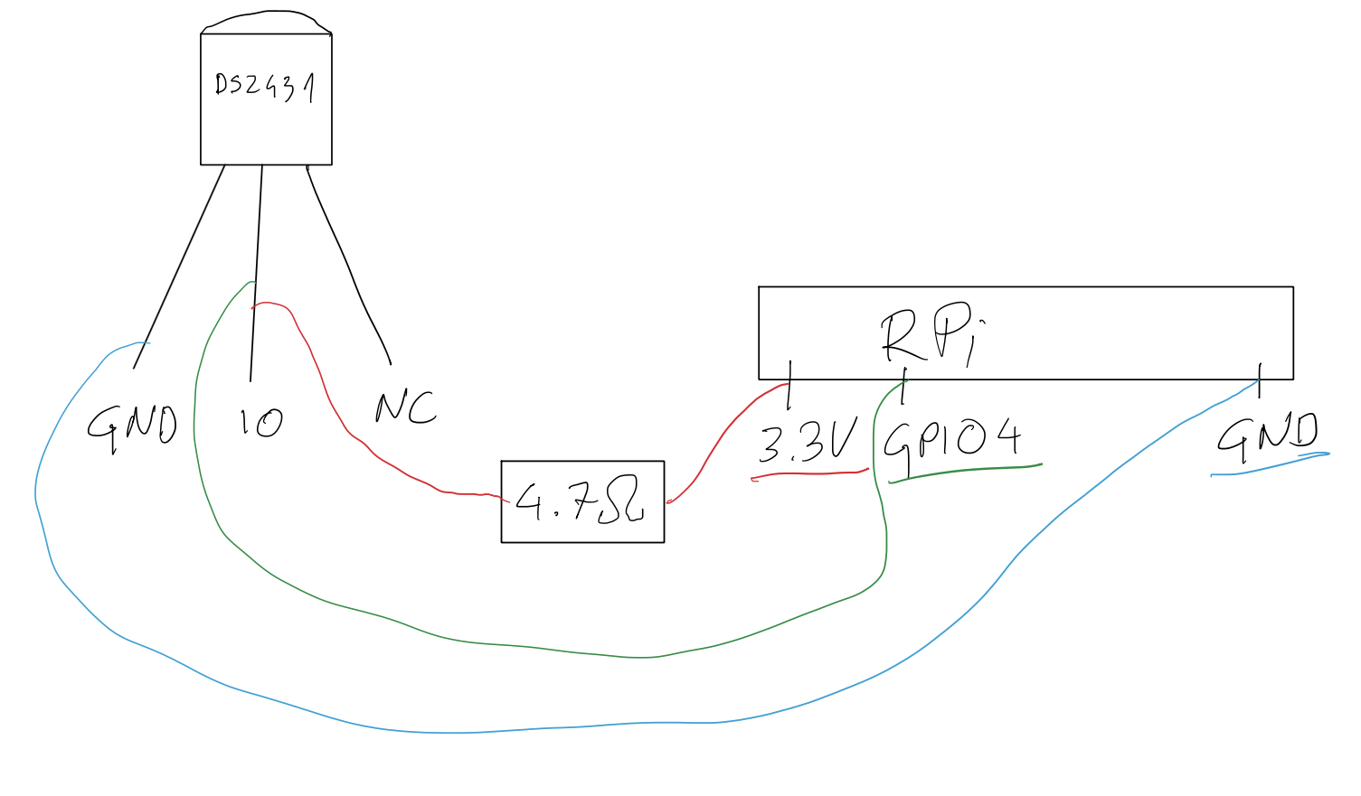
enter image description here

Now the software part. I'm using fresh installation of Raspbian Stretch Lite from 2018-06-27 on Raspberry Pi 3B+, SSH enabled.

First run sudo raspi-config, go to 5 Interfacing Options and then P7 1-Wire, answer Yes then reboot.

Alternatively you can edit /boot/config.txt file and put that line at the end: dtoverlay=w1-gpio and reboot.

Now ls /sys/bus/w1/devices you should see two folders/links here:

w1_bus_master1 and 2d-000022b489f8 (name may vary, but must start with 2d-, if it starts with 00- or you have only w1_bus_master then something's not connected properly).

Now sudo modprobe w1_ds2431. After this cd into your 2d-* directory and after you do ls you should see file named eeprom there (it will only appear after modprobe w1_ds2431 so that's important step). This is your point of entry.


To write into the eeprom: echo 'Hello world' | sudo tee eeprom (we need root privileges to write, so we use tee command here).

To read from eeprom: cat eeprom | hexdump -Cv (no root needed).

Example output:

pi@raspberrypi:/sys/bus/w1/devices/2d-000022b489f8 $ echo 'Hello world' | sudo tee eeprom Hello world
pi@raspberrypi:/sys/bus/w1/devices/2d-000022b489f8 $ cat eeprom | hexdump -Cv
00000000  48 65 6c 6c 6f 20 77 6f  72 6c 64 0a 00 00 00 00  |Hello world.....|
00000010  00 00 00 00 00 00 00 00  00 00 00 00 00 00 00 00  |................|
00000020  00 00 00 00 00 00 00 00  00 00 00 00 00 00 00 00  |................|
00000030  00 00 00 00 00 00 00 00  00 00 00 00 00 00 00 00  |................|
00000040  00 00 00 00 00 00 00 00  00 00 00 00 00 00 00 00  |................|
00000050  00 00 00 00 00 00 00 00  00 00 00 00 00 00 00 00  |................|
00000060  00 00 00 00 00 00 00 00  00 00 00 00 00 00 00 00  |................|
00000070  00 00 00 00 00 00 00 00  00 00 00 00 00 00 00 00  |................|
00000080

To make w1_ds2431 module loaded on boot (so there will be no need for modprobe w1_ds2431 each time RPi is rebooted) edit /etc/modules file and add this line: w1_ds2431. With this in place eeprom file will be ready to use automatically after reboots.

Hope it would help someone as I was looking all over internet for how to use DS2431 with RPi and all I found was that darn thermometer :D

5
  • 1
    I was about to upvote, but the +5V in the picture made me step back. That is a cardinal error. You must use +3.3V, anything else is going to fry the BC2835 at least on the long run.
    – Janka
    Commented Sep 26, 2018 at 21:41
  • @Janka As I stated in postscriptum you can just switch to 3.3V and it will be fine. And no, 5V will not fry. RPi is fragile but not so much, don’t worry :) Anyway in general you're right, 3.3V should be advised as proper way of doing things. I've fixed my drawing as well as description. Thanks for input :)
    – Vir
    Commented Sep 27, 2018 at 0:41
  • 1
    The inputs of the BCM2835 are not 5V tolerant.What you are doing if you connect them to 5V is running continous current through the high-side protection diode of that pin. It's not made for that, it should only protect the chip against ultra-low-current static spikes. The diode will eventually wear out and fall short, most likely when the chip runs hot for another reason.
    – Janka
    Commented Sep 27, 2018 at 2:38
  • Ok, noted :) It didn't fry my RPi instantly (like shorted 24V did with my other board) so isn't the 4.7K resitor in combination with internal pin's resitor creating voltage divider? I mean I know the main reason of that 4.7K there is to pullup to VCC but isn't it possible that we have also side-effect in form of divider? I'm still learning this stuff, so just asking here. You're still right that 3.3V in case of RPi should be used, I've first prototyped that solution on Arduino and thus just moved what was working without consideration. Later on I checked 3.3V and it worked :)
    – Vir
    Commented Sep 27, 2018 at 9:49
  • Which internal resistor? The pullup to +3.3V? That one is shorted by the high-side protection diode as soon you apply +5V to the pin from outside.
    – Janka
    Commented Sep 27, 2018 at 9:57

Not the answer you're looking for? Browse other questions tagged or ask your own question.