I have a MEMS Digital Microphone with PDM output. I am planning to use this:
Based on my research, PDM output signals have high-frequency ranges; usually in MHz. To be further processed, it must be filtered/decimated with the use of CODEC. I am planning to use the WM8731.
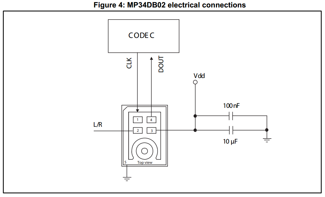
Based on the datasheet of the digital microphone, typical connection is as follows:
However, I do not exactly know as to what exact pins do the Digital output of the mic to be connected, and also the clock signal. Can anyone help me out with this?
Also, I understand that the Raspberry Pi Zero W can communicate with the CODEC via I2S. And to do so, I must utilize the SPI pins of the Rpi. However, still same questions arise as to what exact pins on the WM8731 CODEC should I connect the SPI signals to.
Thanks.

