It is very likely that your module circuit is similar to that below.
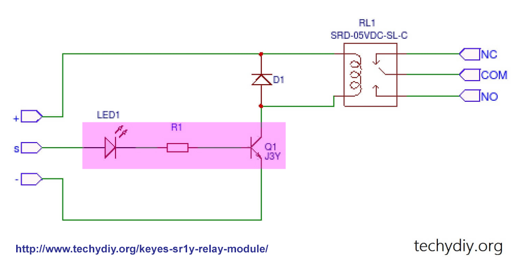
Module spec says 5V High to trigger.
That means S input expects 5V to trigger. If your Rpi GPIO outputs only 3V3 actually a bit less), then the current through Q1 is not big enough to turn on the relay. The Led still turns on BUT NOT FULLY ON!
To prove that my guess is correct, you can do the following.
Disconnect Rpi GPIO from input S.
Use a jumper wire to connect input S to 5V, relay should turn on, with an audible click.
Then connect input S to 3V3, then blue led should grow brighter, the relay might turn on (because 3V3 is a bit higher than you GPIO signal). If relay is still not on with 3V3, then you need an external device to shift your GPIO signal higher, to above 4V perhaps.
There are many ways to level shift up your GPIO's 3V3 level signal to 5V0 level. You can google SE for more info.
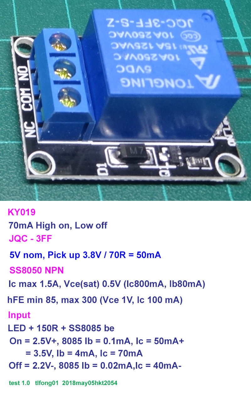
I show below one similar relay module. I did the test without connecting to the rpi (especially not connected to the 5V pin on the RPi 40 pin socket. My module uses a different coil and NPN transistor instead of PNP. But I think the electrical characteristics should be very similar.
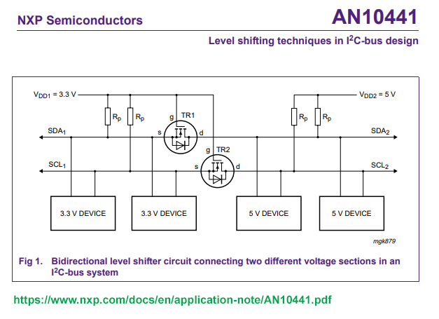
There are many ways to do level shifting. I first learnt the idea from NXP
https://www.nxp.com/docs/en/application-note/AN10441.pdf
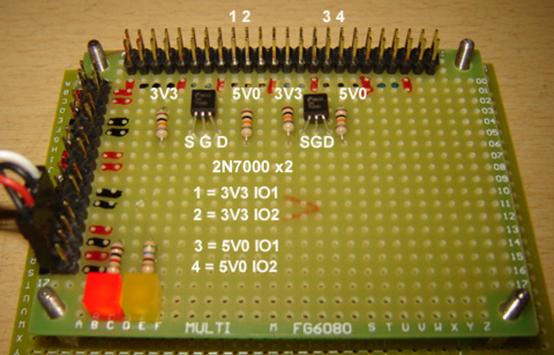
Then I assembled a I2C level shifter using 2N7000.
Then I tried the MCP23017 io expander, and mux 4 of them, so that I can control 64 relays together.
You can get the idea of the i2c mcp23017 way from below.
https://electronics.stackexchange.com/questions/279411/mcp23017-to-control-a-relay-board-failing-when-6-or-more-relays-are-active
The above are a bit challenging and might take you weeks to catch up. If you are in a hurry, I would suggest you AdaFruit or SparkFun's tutorials for beginners. They also sell newbie friendly modules to help you jump start.
Actually logic level shifting might not be the easist solution for you. You may consider throw away your BJT transistor input module and get photocoupler based module. Then you can keep you gpio pin signal at 3V3 logic level, and the 5V0 power at JD Vcc is strong enough to energize the coil.
There are many advantages of using photocoupler. You might like to google to know more.
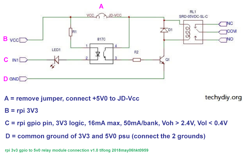
Logical level shifting using HCT125
If you find ic2 stuff too hard, you may like to try the easier HCT125. Adafruit has a good tutorial, and rpi example. I have been using HCT125 in some of my project, using 4 chips to up shift 16 rpi gpio pin signals. You can use OE to disable and mux to as many pins as you like. But the wiring is a bit messy.
74AHCT125 - Quad Level-Shifter (3V to 5V)
https://www.adafruit.com/product/1787
... Level shifting chips let you connect 3V and 5V devices together safely.
... particularly good at converting 3V logic up to 5V.
... We have a wiring example for Raspberry Pi here
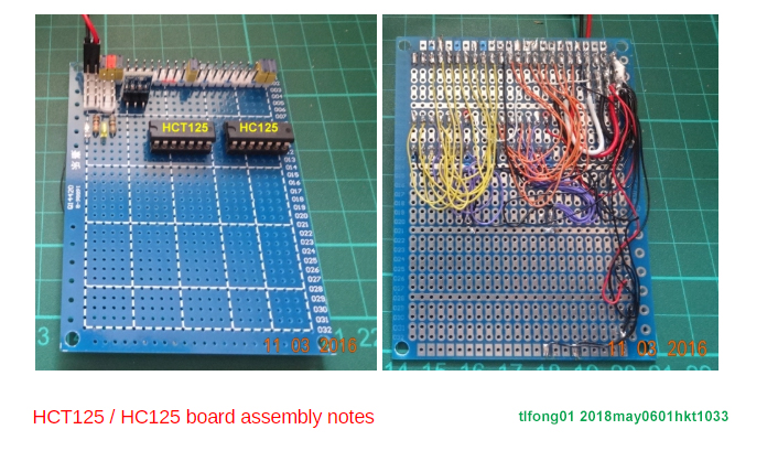
Logic Level Up Shifting using HC04
As I said earlier, different approaches have different pros and cons, and you need to make an engineering tradeoff, or cost benefit analysis. If you wish to control 128 relays placed far far away, I2C MCP23017 is good; if you want to Mux/OE (Output enable/disable) the relay modules, then HCT125 is good; if you wish to up shift to different levels (not just 3v3 to 5v0, but 3v3 or 5v0 to 12/24/36V, then HC04 Quad Open Drain NAND gate is good. I tried HC04 the other day for a 817c photocoupler driven relay module and found it working OK.
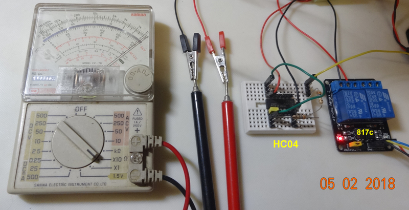
Up shifter using 2N2222
And if you want to entertain only one relay module, then the 4 shifters in 1 chip HCT125/HC04 is a waste or overkill. Then you may consider single transistors (such as BJT NPN 2N2222, MosFet 2N7000). I tried 2N2222 the other day and found it OK.
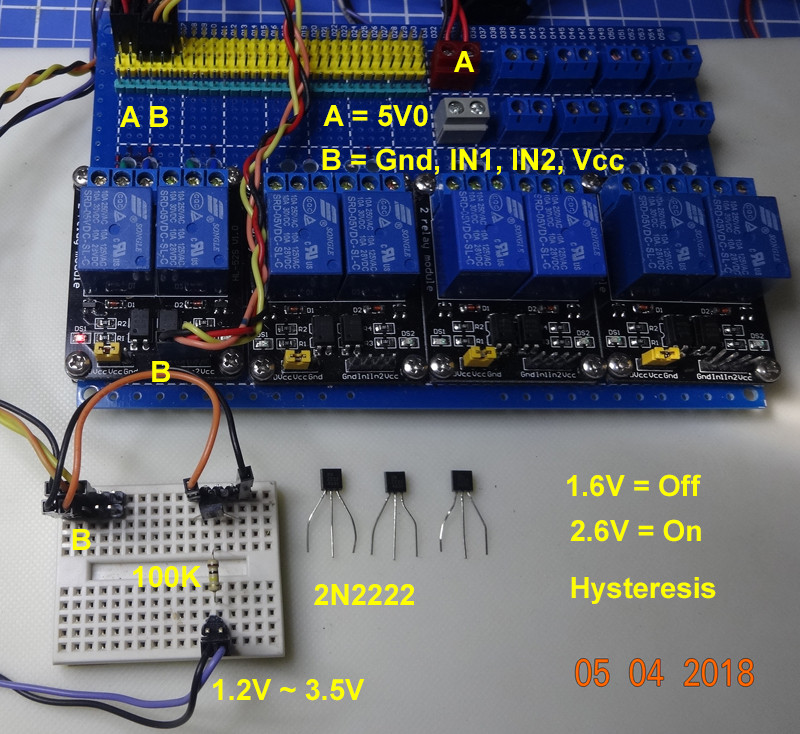
DIY your own module using 2N2222
If you are a DIYer or maker, and you want to build everything yourself, then you can use a Songle or
How does an Electric Relay work?
http://www.techydiy.org/how-does-an-electric-relay-work/
Built Your Own 5V Relay Module [using 2N2222, driven by rpi] - Nick Momrik 2017jul05
https://nick.blog/2017/06/22/5v-relay-module/
...
/ to be continued, ...


