6

According to the answer to Where is the USB2 OTG port on the RPi 4 Model B located? the Raspberry Pi 4B has a "hidden" OTG port in the USB-C power connector. I found at Very simple OTG on pi4 and at 4 ways to connect your Raspberry Pi 4 to the internet how to use the USB2 OTG port just with a simple USB cord. But this is very unstable because the USB port on the connected laptop cannot provide enough power (2.5A - 3.0A).

My first idea to use this port was to power the RasPi through the +pin and GND pin on the GPIO pins to use the OTG port. But I don't want to bypass the polyfuse on the USB-C power connector. I also do not have a POE (power over ethernet) HAT to power the pi this way. So I'm looking for an Y splitter cable for this port so I can power the RasPi with the power supply but also can use the OTG port.

Is it possible to make such an Y splitter cable? If so, how to make it? Or is there a better alternative? A simple drawing would be nice.

7
  • There is no polyfuse. The schematic shows 5V directly connected to the power management chip.
    – Milliways
    Commented Jul 15, 2019 at 7:21
  • @Milliways Really? The power connector of the RPi 4B does not have a polyfuse anymore? It is completely unprotected now?
    – Ingo
    Commented Jul 15, 2019 at 7:25
  • 1
    Well I haven't examined the board, but there is none shown on the schematic between VBUS and the transient protection diode (which is the only place it would make sense). Frankly, it never made much sense from an engineering point on any of the current series.
    – Milliways
    Commented Jul 15, 2019 at 7:32
  • @Milliways Thank for the information :-) But polyfuse or not - it doesn't affect the question.
    – Ingo
    Commented Jul 15, 2019 at 7:53
  • You can DIY your own polyfuse: raspberrypi.stackexchange.com/questions/98715/…
    – tlfong01
    Commented Jul 15, 2019 at 9:03

2 Answers 2

7

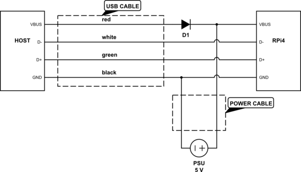
The problem here is that the RPi 4 USB-C connector is hard-wired as an upstream-facing port, which urges the host device on the other side to provide power. Yet if you power the RPi from an independent power supply (using an Y-cable or via the 5V pin), this supply will be connected in parallel to the host device's 5V output, which is problematic.

The simplest solution would be to make a cable which only conveys USB data signals (and ground) but not 5V. However, such a cable wouldn't behave in strict compliance with USB if plugged into an unpowered RPi, because signals on D+/D- lines may then have higher voltage levels that VBUS. Personally I'd add a diode feeding some voltage from host to the RPi (which, as you said, won't likely be enough to power the RPi anyway), just to cover this case. Here's how an Y-cable could look like:

schematic

simulate this circuit – Schematic created using CircuitLab

You still shouldn't plug the cable in the RPi while the PSU is off, because that would result in the overcurrent on the host USB port, but at least that won't damage the RPi. If you're careful about always plugging the PSU first, you could omit the diode (leaving VBUS line disconnected).

The power cable could also be connected to 5V/GND pins on the GPIO connector, which will correspond to the same circuit when the USB-C connector is plugged in.

6
  • If you add a diode to the connection between the PSU and the red wire, you will form a "wired OR" connection, and then no worries about back-feeding PSU from HOST or RPi. Also, many diodes (Si) have a 0.7 Volt drop which may be enough to "upset" the RPi. A Schottky diode will reduce this to ~0.3 V.
    – Seamus
    Commented Apr 19, 2020 at 1:07
  • remove the diode at all, PC supply is not enough to power the pi anyway, just plug the PI power supply BEFORE plugging it to the PC
    – Phil
    Commented May 21, 2020 at 16:50
  • made this, i.imgur.com/XaCSjMM.png it does not work so far...
    – Phil
    Commented May 21, 2020 at 18:53
  • @fdsfdsfdsfds: Did you ever get this cable to work as advertised? If not, what does "not work" mean exactly - have you taken measurements?
    – Seamus
    Commented Mar 13, 2021 at 7:00
  • The statement "However, such a cable wouldn't behave in strict compliance with USB if plugged into an unpowered RPi, because signals on D+/D- lines may then have higher voltage levels that VBUS" is at best confusing and possibly wrong. In this context the USB2 OTG port the Pi IS the USB device and expected to receive power (which is undesirable).
    – Milliways
    Commented Feb 11, 2023 at 4:49
2

Seamus is right mentioning the significant voltage drop across that diode. If you are concerned regarding D+ or D- getting a higher voltage than VBUS (which might indeed lead to a destructive effect called "latch-up"), I would recommend to use Schottky diodes (like Seamus suggested), but connect them like shown in this crude schematic:

schematic

simulate this circuit – Schematic created using CircuitLab

2
  • The voltage drop is only significant if there's current through the diode. In my answer, the diode is normally closed, it only opens if you forget to power the Pi properly. Commented Mar 10, 2021 at 7:59
  • 2
    Also, I bet you (and the person who upvoted your answer) didn't actually try this schematic, did you? Schottky diodes on USB data lines will exceed the allowed line capacitance by an order of magnitude. Commented Mar 10, 2021 at 9:35

Your Answer

By clicking “Post Your Answer”, you agree to our terms of service and acknowledge you have read our privacy policy.

Not the answer you're looking for? Browse other questions tagged or ask your own question.