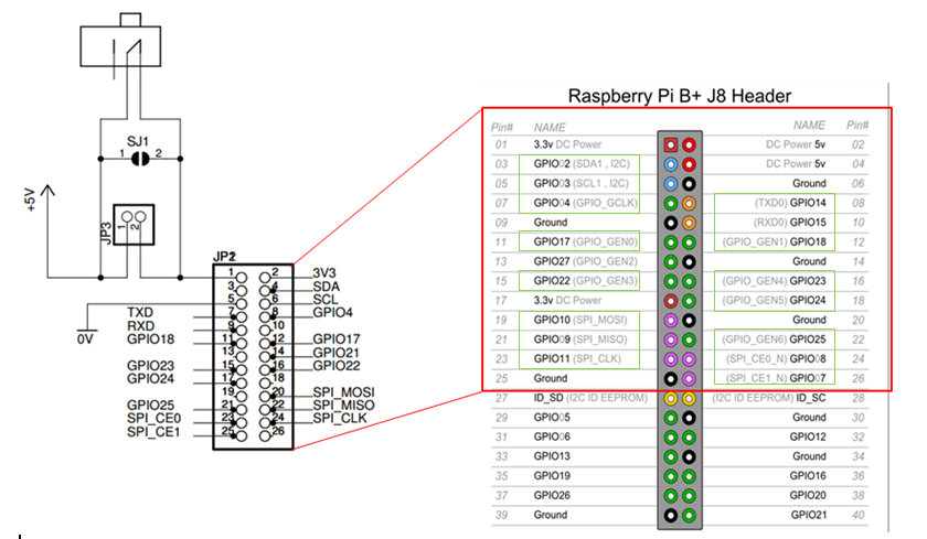
I am studying the schematic diagram of the Raspberry Pi to Arduino shield from cooking hacks and I noticed that there is an inconsistency in the labeling of the pins. So, this gives me two questions. Top view of the shield:
Bottom view of the shield:
(Both photos taken from their website)
I was creating my own guide for the pin layouts and where they go so that it will be easier and faster to check later on. So this image shows the bottom connection of the shield(left) that attaches to the GPIO ports of the RPi(right). I also marked up to where the shield takes up the GPIO ports(red).

So finally, my questions are:
- If you look at GPIO pins 17,21,22; then look to where it connects to the RPi which is labeled 17,27,22 correspondingly. Is this just a typo on cooking hack's end?
- Do pins like 14,15,18,23,24 and the rest make a direct connection? If for example i connect a wire on the SDA pin on the shield, is it like i'm connecting directly to the GPIO02(SDA1, I2C) of the raspberry pi?
This is the page for the shield: https://www.cooking-hacks.com/documentation/tutorials/raspberry-pi-to-arduino-shields-connection-bridge


