1

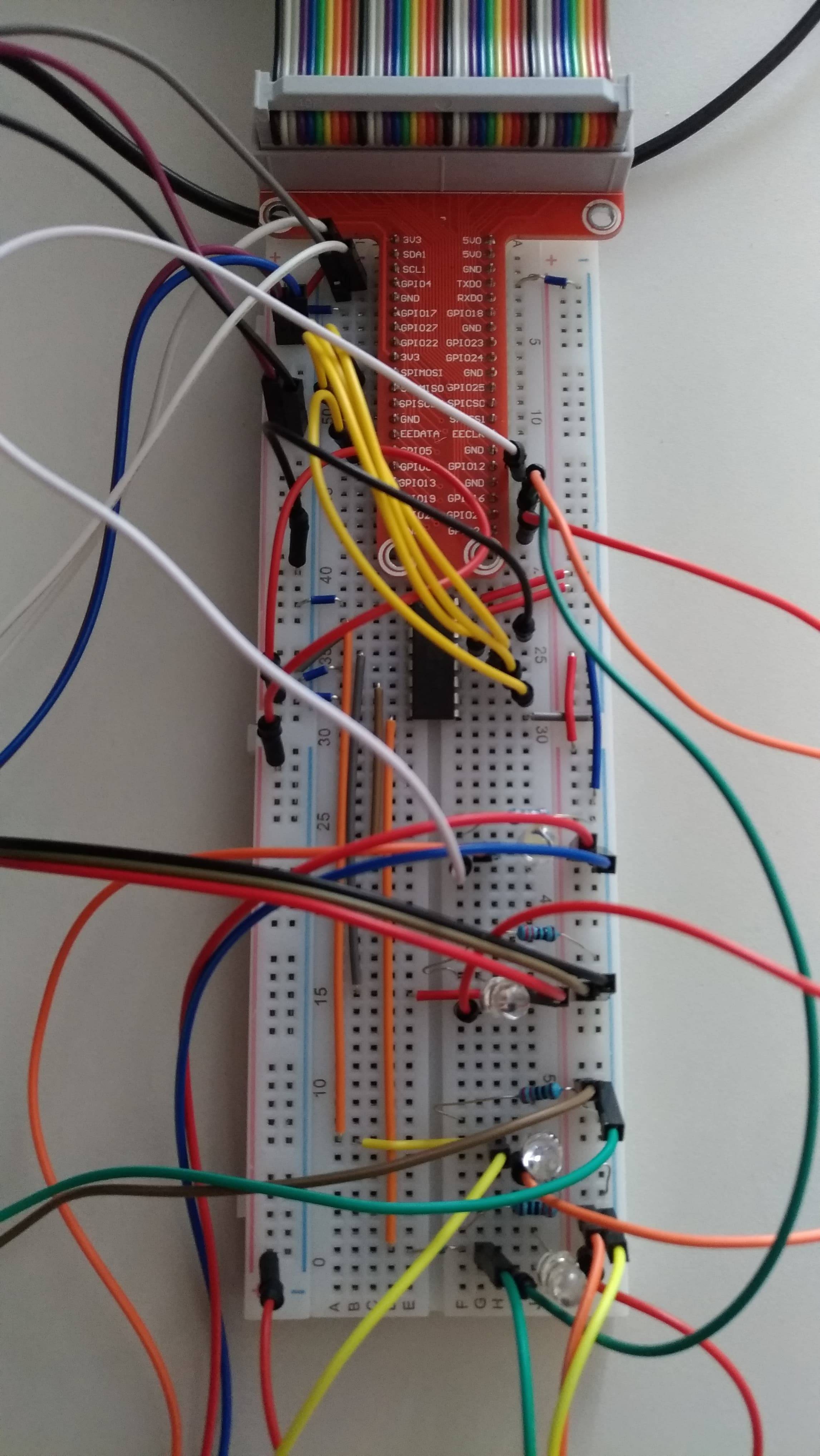
I'm doing a project for a school assignment and have some issue with my circuit. When I connected the breadboard to pi and to power, everything was working, I could read data from sensors and looked fine. However, after 30-50minutes my pi stopped working and a green LED is dead. I believe I have burnt my new pi. I just want to know what happened, what I'm doing wrong before I'll try to run this on a new pi. First of all, I would like to ask if there's a limit to wired sensors/devices because I'm using a few. Maybe it was an issue?

Let me describe my circuit:

  • Serial LCD wired to SDA, SCL
  • DHT11 temp&hum wired to GPIO4
  • MCP3008 wired to MOSI, MISO, SCLK, GPIO5. I'm using only 1,3,5,7 channels. unused are wired to GND to reduce the noise. Used channels go down on the breadboard and are connected to soil moisture sensors (please see attached picture).
  • 4 soil moisture sensors connected to analog inputs in MCP
  • 4 diodes (red, green, blue, white), 4 resistors 220 R, each diode connected to GPIO to manage them from phone app I'm wiring 3V3 output to + in the breadboard and every sensor/device is wired to this power. I'm wiring 2x GND outputs to - (left and right side of the breadboard).

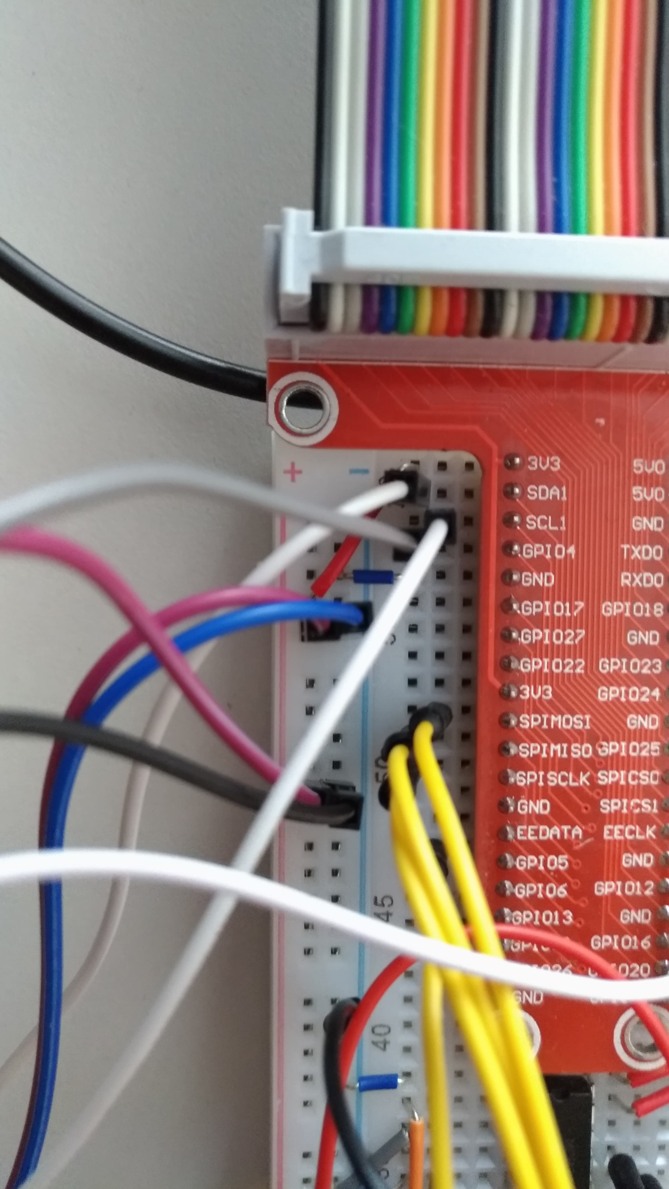
Please see attached pictures: circuit with mcp, dht11, lcd, leds enter image description here

2 Answers 2

1

Question

Why Rpi burnt?

Circuit: Serial LCD, DHT11, MCP3008, ...

After 30-50 minutes pi stopped working, green LED dead. have burnt my new pi.

if there's a limit to wired sensors/devices because I'm using a few.

Answer

The root cause might be you are using 3V3 Rpi to talk to 5V0 guys.

I read your question and found nothing wrong. I also use the devices like yours, perhaps twice more.

But there is a catch - I never direct connect Rpi 3V3 GPIO signals to outside things. I almost always use a logical level shifter, converting Rpi's 3V3 signals to 5V and interface with outside things.

For example, I play with I2C LCD shown below.

enter image description here

I know these LCD are almost always Arduino compatible (I played with them in my Arduino days) - In other words Vcc = 5V. That means it is NOT Rpi compatible. The chip PCF8574 is very likely Vcc = 5V. I am pretty sure, because I never apply Vcc = 3V3 for the LCD and all the other I2C SPI guys.

I am not suggesting you to use logical level converter, like me. But if you direct connect Rpi 3V3 GPIO to 5V devices, it might work for some time, but sooner or later it will burn.

You might also like to read the following post about another unlucky guy burning his new Pi.

DHT11 sensor and the wrong voltage may have fried my RPi3

To summarize, if you connect Rpi GPIO even through a resistor to 5V, then Rpi might have its life shortened, if not burnt immediately. The picture show why DHT11 with Vcc = 5V might be a problem. See my answer in the above post for more details.
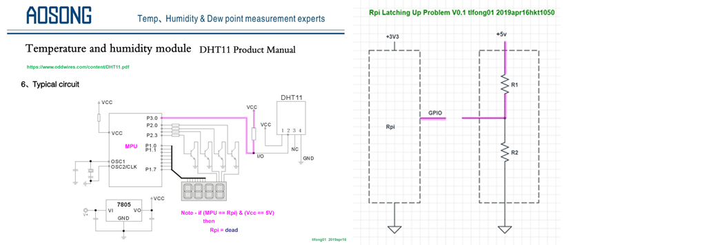
DHT11 latching up

Tips on using DHT11

  1. You can use Vcc = 3V3 if your cables are only 20cm short.

  2. You can use cables 20 meters long if Vcc = 5V.

  3. DHT11 is slow and needs a couple of seconds to complete a job. So if you ask too frequently, it will go crazy and give you nonsense answers.
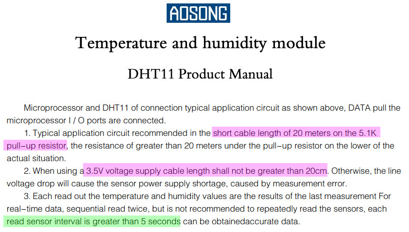
DHT11 Tips

Pull-up Resistors Tutorial - Electronics Tutorials

Datasheets

8-channel Bi-directional Logic Level Converter - TXB0108 USD$8.00

4-channel I2C-safe Bi-directional Logic Level Converter - BSS138 US$$3.95

DHT11 Datasheet

PCF8574 Remote 8-Bit I/O Expander for I2C Bus (used in I2C LCD modules)

MCP3008 Datasheet - MicroChip

MCP3008 Datasheet reading notes - tlfong01 2019apr09

GPIO Spec and Electronic design checklist

Everything You Want to Know About Raspberry Pi GPIO: But Were Afraid to Ask

Understanding GPIO Outputs (Current Limits)

GPIO Electrical Specifications Raspberry Pi input and output pin voltage and current capability

Electronics design checklist

Make a (electronics hobbyist) Workshop on a Budget for Under £100 - Robin Mitchell 2016may29

References

Note to the OP - The stuff below are rather advanced. So just skim through to get a very very rough idea.

Warning on dangerous pulling up GPIO pin to 5V

GPIO Electrical Specifications Raspberry Pi input and output pin voltage and current capability - Mosiac Documentation Web

GPIO pin circuitry

The internal diodes shown in the figure are not really substrate diodes, but they are actually parasitic FETs. 

Electrically, their I-V characteristic looks like a diode's, but with a greater forward drop and a more gradual knee. 

They may protect against low current transient events caused by transient out-of-range voltages applied to the pins, but they are not intended to protect against the application of voltages greater than the supply voltage or less than ground, even with an external series resistor

In brief, you should never deliberately forward bias those "diodes". Consequently, you can not safely place an external pull-up resistor to 5V on the I/O pin. That would forward bias a parasitic FET and owing to its poor internal impedance to the chip's internal power rail it may overheat, or worse, it may bias up parts of the chip to voltages greater than they can handle. 

So, don't do it!

Latch-up - Wikipedia

Parasitic structure - Wikipedia

3
  • I followed my friend's instruction who told me "Never use 5V in PI" even though tutorial about i2c lcd said 5V. I just thought that 3V3 will be safer. What I'm gonna do is connect lcd to 5V. The question is should I connect DHT to 5V as well? In datasheet is 3.5~5.5V DC so 5V seems proper. Am I right? Can I connect lcd directly to 5V RPI output or should I use logic converter?
    – pisar
    Commented Apr 26, 2019 at 14:18
  • Yes, your friend is right, never use 5V in pi. The LCD tutorial are usually from Arduino days when everybody is using 5V. About logic level converter I always listen to this guy - ​"An ounce of prevention is better than a pound of Cure": Benjamin Franklin.
    – tlfong01
    Commented Apr 26, 2019 at 14:32
  • I have updated my answer with the following references: GPIO in general, GPIO voltage and current limits, electronic design checklist. You might like to read them at your leisure time.
    – tlfong01
    Commented Apr 27, 2019 at 3:34
2

There is no practical limit to the number of digital and analog connections you can make. There are some logical limits, such as having enough chip selects for SPI, enough addresses for I2C and enough pins for GPIO, but this is not a problem here.

There is, however, a limit to the power you can draw from the supply voltage rails. Both the 3.3V and 5V rails have current draw limits. If you exceed the limit a few things might happen - fuses might blow or voltages might collapse. Neither of those scenarios are particularly destructive. One destructive scenario is that the voltage might become marginal - it's possible that a marginal or fluctuating supply voltage could cause damage, either to the microprocessor itself or to the SD card, both of which are susceptible to poor voltage regulation.

Given that you're running everything off the 3.3V rail, and this rail is not particularly beefy, that would be the first place to look - calculate your total current draw and compare to the rail's capability.

But all these scenarios are probably just as likely as a freak occurrence. Given that your setup worked for so long before failing, it's possible the number of devices is not related - perhaps there was a momentary short, a supply surge or any of many freak incidents.

Unfortunately it's very hard to determine the root cause from the information you have given, but here's a good plan of attack:

  1. Do the power consumption calcs.
  2. Check how the LED failed - is it short or open? If it's short, maybe it was the root cause, bringing the Pi down with it.
  3. Check the Pi without any peripherals attached. Does it boot, and if not, what seems to be the problem.
  4. Using all these results, try to narrow down the root cause.
5
  • Hi Heath, Your response is specific however, I'm a beginner. Tried to follow your steps but: 1. I don't really know how to do calcs. I believe I should see the specification of a sensor and sum consumptions. But I cannot find some specs. Or maybe I should measure that? And also how I can find rail's capability? I found that my LCD should be connected to V5. [link[opencircuit.nl/ProductInfo/1000061/I2C-LCD-interface.pdf[/link] Can it be a cause? 3.PI without any peripherals attached doesn't work. It's not an SD card fault because I put this card into another pi and it was booting.
    – pisar
    Commented Apr 26, 2019 at 13:41
  • @pisar Yes, anything Vcc = 5V might kill Rpi. DHT11 Datasheet oddwires.com/content/DHT11.pdf
    – tlfong01
    Commented Apr 26, 2019 at 13:48
  • "I believe I should see the specification of a sensor and sum consumptions.". That's it! "But I cannot find some specs" well then you're stuck - you'll just have to cross your fingers. No, the LCD requiring 5V is only a problem for the LCD, not the Pi. @pisar's well meaning post has it all backwards. If you connect 5V to the LCD, you will definitely damage the Pi without proper level shifting. It's more and more likely that you're overloading the 3.3V rail. Use 3.3V devices, or 5V devices with a level shifter. Commented Apr 26, 2019 at 21:49
  • Good answer +1. It would be even better if you included the actual number for the current limit on the 3.3V rail.
    – Seamus
    Commented Apr 27, 2019 at 12:40
  • Unfortunately "it depends". OP would need to specify Pi details. Commented Apr 27, 2019 at 13:06

Your Answer

By clicking “Post Your Answer”, you agree to our terms of service and acknowledge you have read our privacy policy.

Not the answer you're looking for? Browse other questions tagged or ask your own question.