6

I have two Model A+ Pis and a Model B+, as well as a couple of USB A-to-A Male cables. I want to be able to have the A+es able to communicate over serial to the B+. The reason I'm doing this is because I also have some camera modules, and I want the A+es to take pictures, extract some information, and send a summary over the cable for further processing.

Is there any way to switch the A+es into USB Device Mode so they'll be detected as a serial peripheral (like an Arduino would be) when I plug them into the B+ using the A-to-A cables?

1
  • 2
    Both boards should have hardware UARTs which you could interconnect directly, simply crossing TX<>RX. Commented Feb 23, 2015 at 22:01

3 Answers 3

3

If you consire Raspberry PI Zero an option, there is tutorial at https://learn.adafruit.com/turning-your-raspberry-pi-zero-into-a-usb-gadget/serial-gadget. Raspberry PI Zero has proper OTG support on both USB ports.

On the software level you'd need kernel with "gadget" drivers compiled as modules, g_serial module loaded and software to communicate over that serial port.

There are high chances that OTG support will land in 4.4 kernel for Raspberry PI, see https://github.com/raspberrypi/linux/pull/1239

3
  • Is there any way to connect USB devices to the Zero while it is, itself, acting as a USB device? If so, then I will accept this answer. Part of the question includes reading data from a webcam on the Pi that is acting as a device. Commented Jan 6, 2016 at 14:14
  • I see no problem in that, but hadn't tried myself. Switching on OTG in kernel doesn't turn off normal USB port behavior, thus you can use the "power" USB port for power and OTG, and the other port as normal USB port for webcam. g_ether would even let your webcome with help of Raspberry PI Zero to become something like IP camera, with motion detect, and other features, whatever you'll be able to squeese out of Raspberry PI processing power.
    – myroslav
    Commented Jan 20, 2016 at 18:15
  • Perfect! I didn't realize it could use both ports independently and thought the entire system had to be configured as either a host or a device. Commented Jan 20, 2016 at 19:41
3

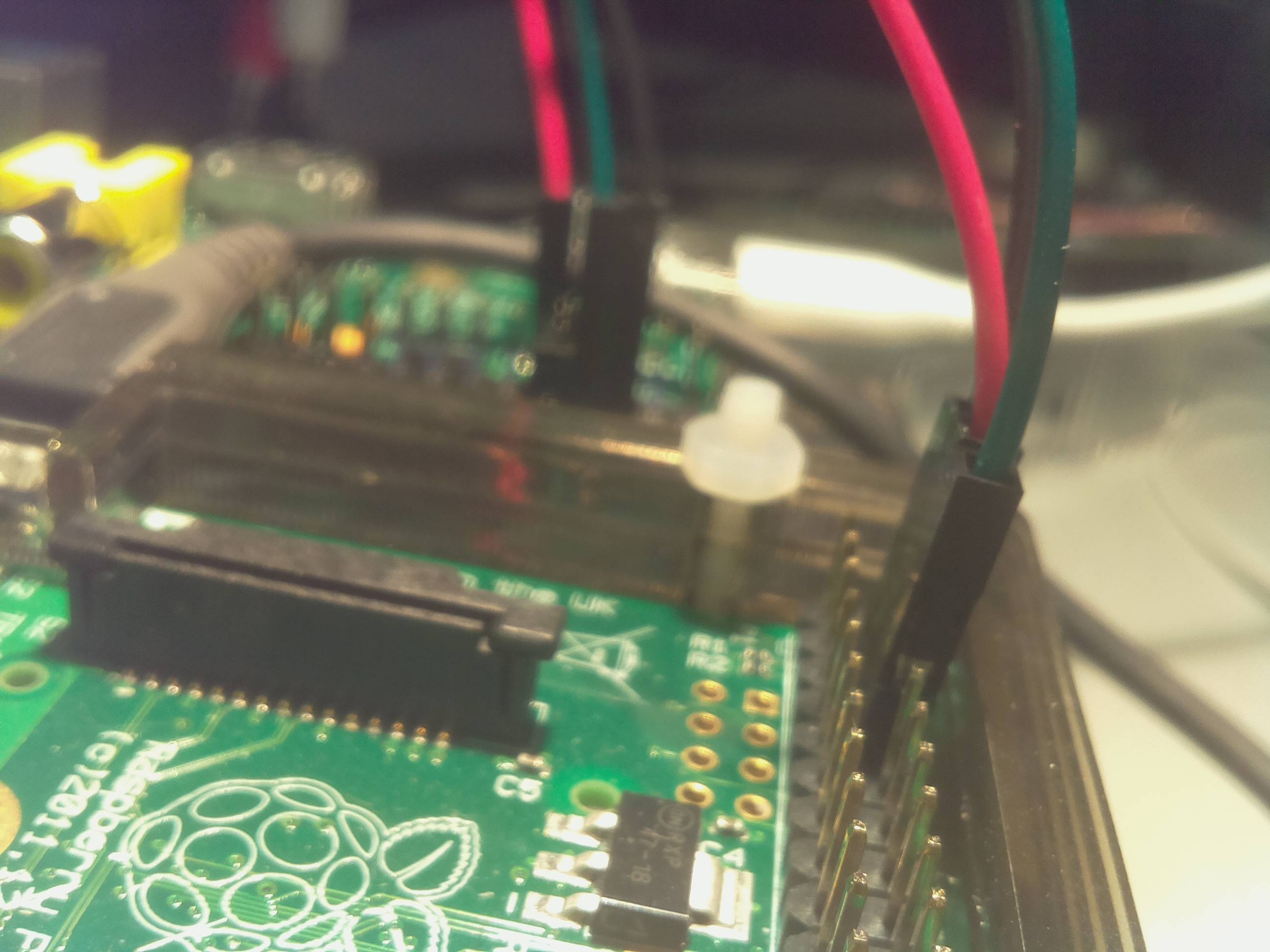
Did you consider connecting the devices directly with simple dupont wires between their UARTs (GPIO Pins 14 and 15) ?

The UART pins are also known as Pins 8 and 10

If you are very adventurous , you can install pppd and even use IP-based tools over the serial link (SSH , FTP etc.) -> See here

1
  • It might be poor form for me to accept this answer, since it doesn't directly address the question... however the original question is an XY problem and this is the best way to address the underlying problem. Thank you! Commented Nov 20, 2015 at 21:18
0

I believe the answer is definitely not for the B(+) and only theoretically for the A(+). See this answer for a concise explanation regarding the former (it comes down to the fact the ethernet jack shares the USB bus).

This Q&A has some more discussion, including the potential of the micro USB power jack (no luck).

The problem with the A models is that there is no system software to support this, or at least, none that's been demonstrated.

1
  • Actually the issue on the B/B+ is not the USB LAN chip itself, but rather the USB hub that sits between the SoC and the outside world to support the USB LAN and the two downstream ports. This can't be made to run backwards in the way that the A's direct connection from the SoC to the external port might be. Commented Nov 20, 2015 at 17:11

Your Answer

By clicking “Post Your Answer”, you agree to our terms of service and acknowledge you have read our privacy policy.

Not the answer you're looking for? Browse other questions tagged or ask your own question.