0

I maybe new to this, but I have the following configuration in place.

Step 1:

(Device 1){RS232}<=======(RS232 to USB cable)=======>{USB}(Pi)

  • I have an RS232 to USB cable attached to the USB port of the Pi and a device which I have named Device 1 on the other end, and it's feeding data that looks like this(Reading in hex):

    F8 CD 0E 0F 00 11 00 00 1C 6D 01 01 8E A4 01 49 A4 91 02 00 44 38 7A 8B EC

  • Now I disconnect the "RS232 to USB cable".

Step 2:

(Device 1){RS232}<=======(RS232 to GPIO)=======>{Pins: RX TX GND}(Pi)

  • Similarly, I attach RS232 port of Device 1 to the GPIO RX TX pins of the Raspberry Pi 3. When I read the data from GPIO pins, it looks like the following(Reading in hex):

    A0 63 2F EF DD FF FF C7 25 FD FD E3 B7 FD 6F B7 DD FB FF 59 85 00

Results:

  • The data received from the USB connection is correct, whereas the GPIO data is not. I expected both of the results to be the same, but they vary I don't know why?!

Here is my code:

#!/usr/bin/env python
import time
import serial

ser = serial.Serial(
   port='/dev/ttyAMA0',
   #port='/dev/ttyUSB0', #used for step 1
   baudrate=19200,
   parity='N',
   stopbits=1,
   bytesize=8,
   timeout=0.050,
   xonxoff=False,
   rtscts=False,
   dsrdtr=False
)
counter=0

while 1:
   x=ser.readline()
   if x:
       print x
       hex_list = ["{:02x}".format(ord(c)) for c in x]
       print hex_list

Could somebody please tell me what I should do to read the data from GPIO and get the same result as the USB data??

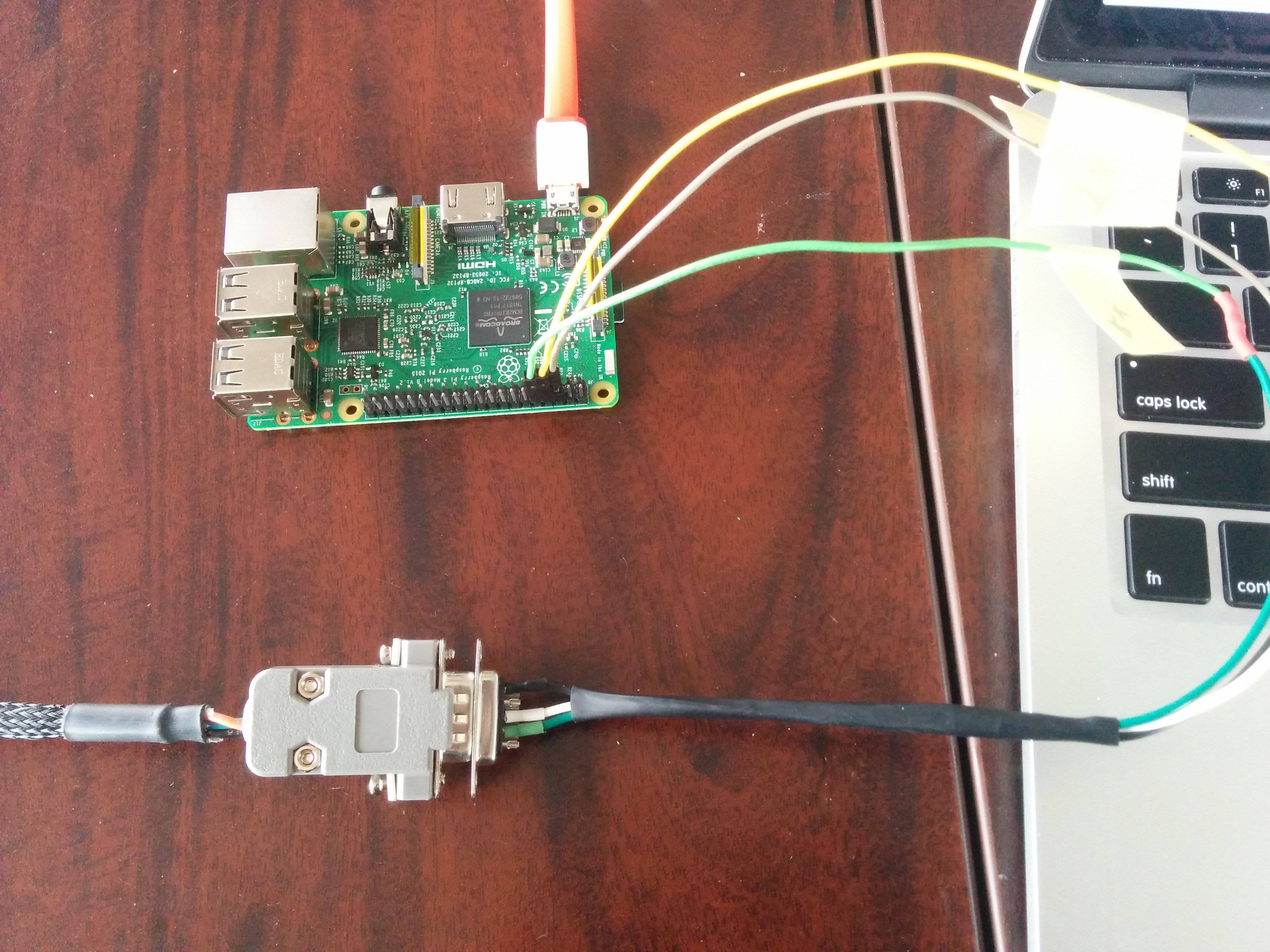
Step 2

5
  • Have you connected the grounds as well as the UART pins?
    – joan
    Commented Jan 16, 2017 at 17:54
  • Yes, I have connected the ground as well.
    – JayB
    Commented Jan 16, 2017 at 17:56
  • Is the other device 3V3? The Pi's UART is 3V3 TTL. You need to post a photo showing the detail of the UART connections between the Pi and device.
    – joan
    Commented Jan 16, 2017 at 17:58
  • 1
    Are you using a level converter from RS232 to gpio? gpio is 3V3 and rs232 is up to +- 15 volts!! Can you describe the RS232 to USB and RS232 to GPIO devices (brand/model)? From your attached image, your rpi/gpio is now dead...
    – fcm
    Commented Jan 16, 2017 at 18:57
  • If you are using a level converter to to convert rs232 levels to pi levels you have to invert the data.
    – PaulF8080
    Commented Apr 29, 2017 at 16:52

2 Answers 2

2

It seems you are missing the critical part of converting RS232 signal (which is not 3.3 V) to RPI GPIO compatible 3.3V Signal as described in this example: https://www.abelectronics.co.uk/kb/article/20/raspberry-pi-serial-port-usage http://raspberrypi.tomasgreno.cz/uart-to-rs-232.html

On GPIO header of RPi you can find a so called UART pins. In fact, it is normal >serial port you know from computers with only one change. UART uses 0 Volts for >logical 0 and 3,3 Volts for logical 1 while regular RS-232 uses -10V for 1 and >+10V for 0. This difference means that when you connect RS-232 device directly to >UART pins, RPi will surely not survive. For this reason, MAX3232CPE integrated >circuit was developed. It is a simple converter that converts voltage levels with >help of few capacitors. To build this, you will need:

You can either create your own converter like this people did: http://justanotherlanguage.org/content/jallib/tutorials/tutorial_serial_port_board

Many circuits will require some serial port communication, you may buy yourself a >rs232 to TTL adapter off the net for as little as $10, or you can build one >yourself. The max232 is a very popular chip. It converts your 5v circuit to the >12v required for serial communication to things like your PC. Many >microcontrollers have RX and TX output pins.

Or buy a converter designed for such purpose: https://cablematic.com/en/products/adapter-raspberry-pi-gpio-txrx-to-rs232-db9-male-MS050/

Specifications RS232 serial interface adapter card in a Raspberry Pi GPIO Tx/Rx system. Ideal for connecting serial devices in a Raspberry circuit: PLCs, industrial >controllers, etc. Transmission frequencyData ion: 230 Kbps. Input voltage: 2.7V to 5.25V. It has male DB9 connector, 4-pin connector, and connection cable.

Good luck

4
  • 1
    This is a bit of a link only answer. When the links die then your answer will not be particularly useful. If you could edit your answer to include the relevant steps/details from the link(s) then that would be great. Otherwise your answer might be flagged for deletion. Commented Nov 21, 2019 at 17:53
  • 2
    I don't think this is a link only answer. I'm able to understand it without opening any links. Commented Nov 22, 2019 at 7:35
  • Although it would be nice if there were a bit more detail, I agree with Dmitry in the sense that even if you remove the links there is enough information left to constitute an answer. Regarding the policy here: raspberrypi.meta.stackexchange.com/questions/842/…
    – goldilocks
    Commented Nov 22, 2019 at 13:01
  • Ok thanks, I will edit to add more info but at the same time no rewrite the external links info. Thanks for keeping the forum as clean as possible. Commented Nov 22, 2019 at 23:04
1

Apart from the voltage mismatch (RS232 is up to ±15V, although most devices which claim to be RS232 use much lower voltage unipolar signals), the polarities are different.

Even if you haven't already damaged the Pi it won't work.

There are RS232 <--> TTL devices, many of which have a 3.3V option.

1
  • MAX3232 chip for example. Read up here and here, for example. Commented Dec 6, 2018 at 9:05

Your Answer

By clicking “Post Your Answer”, you agree to our terms of service and acknowledge you have read our privacy policy.

Not the answer you're looking for? Browse other questions tagged or ask your own question.