I want to add a 5V fan to the RaspberryPi,
I tried to activate gpio pins via /sys/class/gpio export files,
I did not succeed yet, I guess pin 2 and 6 have both direction out ?
Do I have to take care of anything?
I want to add a 5V fan to the RaspberryPi,
I tried to activate gpio pins via /sys/class/gpio export files,
I did not succeed yet, I guess pin 2 and 6 have both direction out ?
Do I have to take care of anything?
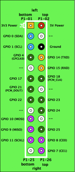
As stated by Marco Poli, pins 2 and 6 are not GPIO, but fixed.
If you are trying to control a fan you will need to connect to a proper GPIO pin, see the eLinux GPIO pinout, you are looking for pin names starting with "GPIO".
If you are trying to power directly from the RPi you can only get around 300 mA, it would be advisable to connect using a transistor as shown in response to this question about 12 v motors, alternatively we sell a board called PicoBorg which is capable of driving 4 fans / motors if you are not happy / interested in building your own circuit.
On a side note we have a script called ChilledPi on our site intended for use with PicoBorg for switching fans on / off with temperature, the code should also be easy to change for driving different GPIO pins if using your own wiring.
Raspberry Pi can run a 2 pin powered 12V Fan. Attach to 5V pin (top right in diagram) and GND to third pin from top right - GND pin in diagram (available here: http://www.cl.cam.ac.uk/projects/raspberrypi/tutorials/robot/cheat_sheet/ )
Turning it on at a certain temperature would require a way of measuring temperature at the heat sinks presumably.

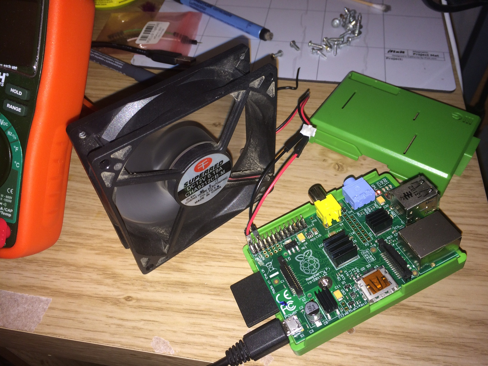
And here is an example of a fan running on my R Pi:

If you attached the fan directly between GPIO and GND, you won't get far. These pins can optimistically source up to 50mA at 3.3V, realistically you shouldn't exceed 5mA draw. A really tiny fan can draw the 50mA, 70-150mA is more viable. At 3.3V the current will be even higher.
Essentially, if you attach a really tiny fan, it might work - barely. If you want something bigger, you'd better attach some driver circuit capable of passing higher currents.
A fan takes from 100 to 200 mA, but 1 GPIO pin will only supply a maximum of 16 mA. If you combine all the GPIO pins you can get 51 mA but thats still not enough. However the power pins can take 500 mA(Model A)/700 mA(Model B) so the best option would be to buy a fan with 4 wires. The blue/black wire is GND, red is 5V VCC, one of the 2 other cables gives the RPM. The last wire lets you control the speed using PWM. This is what PiBorg's boards do, but it doesn't give the RPM of the fan/motor. A 3 wire fan's speed can't be controled.