1

I want to do a what I hope is a simple project. Making a led light clock built into a plank.

Basically I'm planning on cutting 28 slots in a piece of wood, and placing a small LED light in each slot, then covering it all up with a very thin piece of wood that these lights can shine through.

My question is, what is the easiest way to control these lights with a raspberry pi Zero, as I need to control more lights than there are available GPIO pins?

I'm coming from the software side so I have no problem coding the clock or figuring out which of the 28 leds need to be on to display the correct time. But what hardware can I use to control this many Led lights?

If there is something which is close to plug and play I would prefer that, although any solution is great.

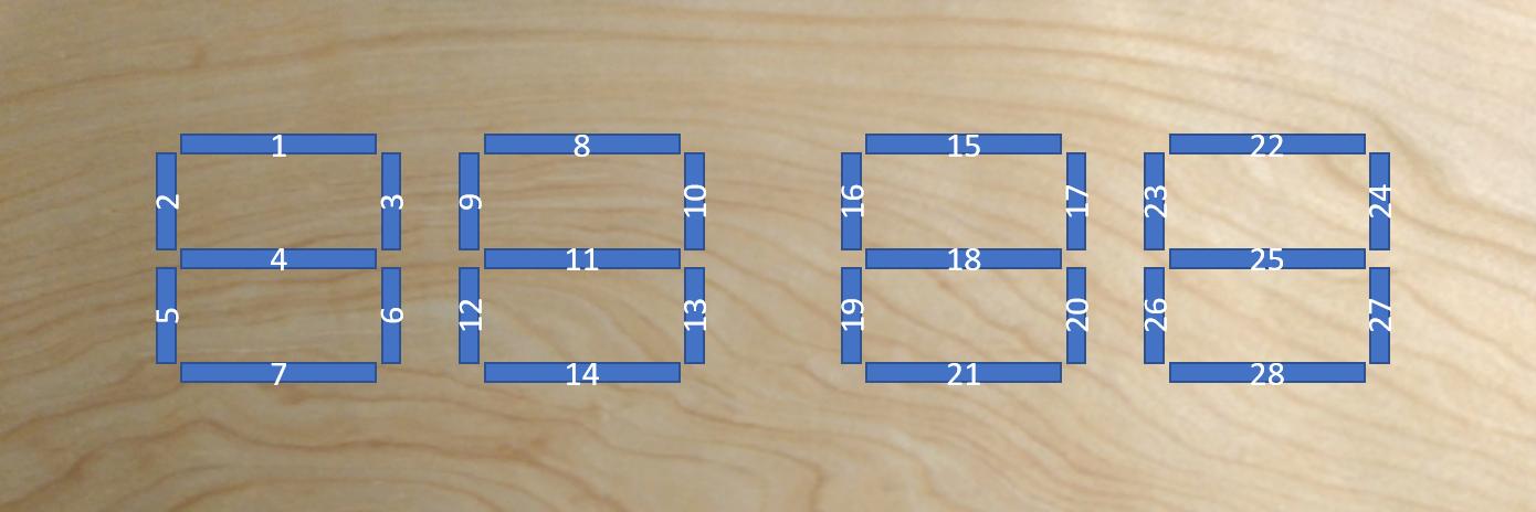
Picture for illustrative purposes. enter image description here

2 Answers 2

1

The only sort of plug and play option would be a LED strip. However I don't see how you could bend a LED strip into the shape you need.

As you probably only want on and off you could use a simple GPIO extender chip. Something like the MCP23017 would let you control 16 LEDs per chip. They use the I2C bus and you could easily add two chips to the bus for your 28 LEDs.

There are probably a dozen other feasible options but I suspect the I2C MCP23017 is the simplest to get working.

4
  • This is probably the way I will go, two MCP23017 will give me plenty of pins, and seem and is just a matter of a little soldering. Multiplexing seems to require a much deeper understanding of hardware.
    – JensB
    Commented Oct 17, 2019 at 12:15
  • 1
    I think so. You need quite a lot of wiring for multiplexing individual LEDs (and diodes I'd guess). The multiplexing link was actually to 7-segment displays. I presume the idea was to use four 7-segment displays rather than LEDs. Have you considered 7-segment displays?
    – joan
    Commented Oct 17, 2019 at 12:26
  • I have, but I could not find any of the size I want. I want each digit to be around ~4 cm tall. And also I'm worried that they wont shine through the wood bright enough.
    – JensB
    Commented Oct 17, 2019 at 15:03
  • The MCP23017 or equivalent makes sense then. The wiring is straightforward and the software fairly simple. The most complex software you will need is deciding which LEDs to switch on/off at each minute.
    – joan
    Commented Oct 17, 2019 at 15:14
1

If you multiplex you only need 11 pins. One side of each segment's LED is controlled by a pin and is bussed with like segments in the other digits (eg, 1,8,15,22). The other side of the LED is bussed with others in each digit and is controlled by a pin (often buffered with a transistor- total digit current can exceed a pin's rating). The key is to continuously scan through the 4 digits quickly (faster the better, but > 30Hz to avoid flicker) while turning on the correct segments for the selected digit.

1
  • 1
    Actually, if you Charlieplex them, you can implement this with only 6 GPIO pins.
    – Glen Yates
    Commented Oct 16, 2019 at 18:07

Your Answer

By clicking “Post Your Answer”, you agree to our terms of service and acknowledge you have read our privacy policy.

Not the answer you're looking for? Browse other questions tagged or ask your own question.