I have a Raspberry Pi Zero W that uses this LCD screen, including its touch interface using SPI0.
What I am trying to achieve is to add another SPI device that uses SPI0. I am able to successfully extend the SPI0 CS signals using an overlay, as described here in order to be able to add my SPI device to the RPi.
In order to test that I can use SPI0 while also using the abovementioned LCD, I am running the following test code, without the additional SPI device attached to the RPi:
import spidev
import time

spi = spidev.SpiDev()
spi.open(0,2)
spi.max_speed_hz = 10000
spi.mode = 0

msg = [0xAB]

while 1:
  res = spi.xfer2(msg)
  print("Result", res)
  time.sleep(1)
This returns [0] as the result for every transmission, which I assume means that the transfer was successful. Probing the signals used by SPI0 with an oscilloscope, I can verify that the corresponding CS and CLK signals are controlled as expected. I can see a clear signal on CLK, but there is no signal on MOSI. When I use the touch screen, I can see activity on the MOSI pin while communication between the LCD and RPi is taking place, so the SPI bus is certainly working - it is just as if I am missing something when I am trying to use the bus.
If I adapt the code to use SPI1, I am seeing the exact same symptom on the SPI1 pins, i.e. expected signals on CS and CLK, but no signal on MOSI (SPI1). Note that I have added dtoverlay=spi1-3cs to /boot/config.txt in order to activate SPI1.
Herewith also my /boot/config.txt:
# For more options and information see
# http://rpf.io/configtxt
# Some settings may impact device functionality. See link above for details

# uncomment if you get no picture on HDMI for a default "safe" mode
#hdmi_safe=1

# uncomment this if your display has a black border of unused pixels visible
# and your display can output without overscan
#disable_overscan=1

# uncomment the following to adjust overscan. Use positive numbers if console
# goes off screen, and negative if there is too much border
#overscan_left=16
#overscan_right=16
#overscan_top=16
#overscan_bottom=16

# uncomment to force a console size. By default it will be display's size minus
# overscan.
#framebuffer_width=1280
#framebuffer_height=720

# uncomment if hdmi display is not detected and composite is being output
#hdmi_force_hotplug=1

# uncomment to force a specific HDMI mode (this will force VGA)
#hdmi_group=1
hdmi_group=2
#hdmi_mode=1
#hdmi_mode=87

# uncomment to force a HDMI mode rather than DVI. This can make audio work in
# DMT (computer monitor) modes
#hdmi_drive=2

# uncomment to increase signal to HDMI, if you have interference, blanking, or
# no display
#config_hdmi_boost=4

# uncomment for composite PAL
#sdtv_mode=2

#uncomment to overclock the arm. 700 MHz is the default.
#arm_freq=800

# Uncomment some or all of these to enable the optional hardware interfaces
#dtparam=i2c_arm=on
#dtparam=i2s=on
dtparam=spi=on

# Uncomment this to enable the lirc-rpi module
#dtoverlay=lirc-rpi
dtoverlay=ads7846,cs=1,penirq=25,penirq_pull=2,speed=50000,keep_vref_on=0,swapxy=0,pmax=255,xohms=150,xmin=200,xmax=3900,ymin=200,ymax=3900

# Additional overlays and parameters are documented /boot/overlays/README

# Enable audio (loads snd_bcm2835)
dtparam=audio=on

# New line added 2022/09/30
hdmi_cvt 1024 600 60 6 0 0 0

# New line added 2022/10/10
dtoverlay=spi-cs-extend
dtoverlay=spi1-3cs
What could be the reason for seeing no signal on the MOSI pins for either SPI0 or SPI1, while the expected signals on the CS and CLK pins appear?
Thank you in advance for your assistance!
UPDATE 1: Comment by joan:
Use piscope to capture the signals
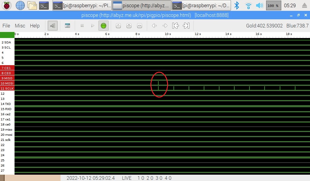
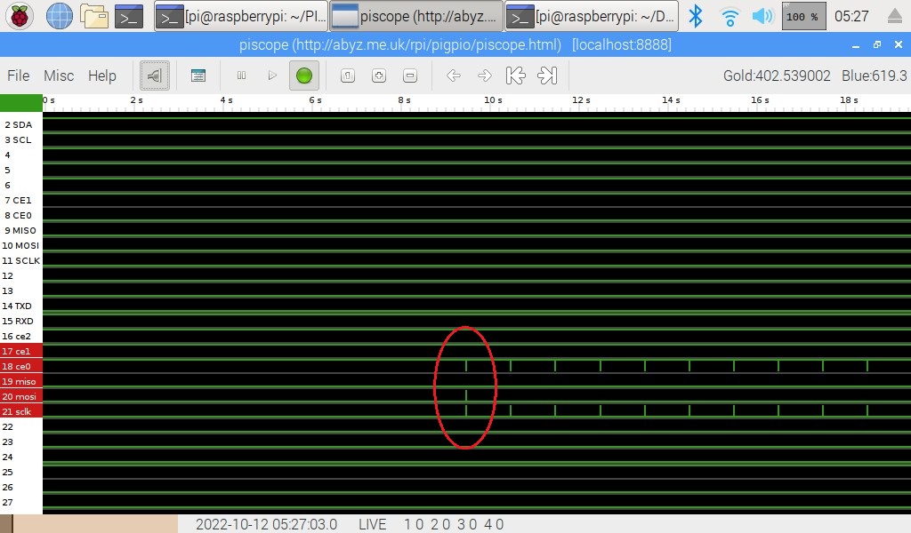
Thank you Joan for referring me to piscope - that tool is a golden treasure! Below are the screenshots that I took using SPI0 and SPI1, as described in the original post above.
Interestingly, there seems to be data on the MOSI line only when the first byte is sent, thereafter there is nothing on the MOSI line. I did not confirm if the data on MOSI for this one byte is correct, though - I am just trying to first get the bus completely up and running.
What could cause the SPI bus to only transmit the data once, and never again after that?
Comment by Gil:
A schematic would be a big help, I do not do well with word problems. MOSI is Master Out Serial In. Is the device whos pin you are referencing expected to return data. If not it will not do anything
As explained in my original post, I don't have the external device connected yet, so there isn't a schematic that I can post at this stage. I am probing the MOSI pin on the RPi directly first to see if the RPi transmits data over the SPI bus. This will make it easier for me to first get the SPI bus running and then continue with further integration, instead of trying to debug a basic SPI bus issue with everything connected and possibly something else influencing my test results.


