7

I have a couple of AD7705 chips I'm attempting to use with my RPi to read the analog pins from a sensor that spits out 0~4V. Nice, detailed datasheet for the ADC is here:

http://www.analog.com/static/imported-files/data_sheets/AD7705_7706.pdf

So far reading over that I think I can figure out how to bit-bang the SPI interface and read values.

I'm fairly new to this world of microelectronics, though, and I'm stuck at something - it appears to me that my ADC needs a stable clock signal that I'm not sure I can create.

It says it can be 'driven by a CMOS clock', is something the RPi can provide? I notice GPIO4's 'alternate' function is GPCLK0, is this what it's supposed to provide?

I'm confused by the results I find searching the big G; it seems that the RPi has various internal clock sources that can be somehow routed to GPIO pins, but the details on how to do that are.. quite thin.

Can someone shed some light on how I'd go about generating this clock signal, using the RPi or otherwise? It seems it wants a 5mhz clock, accepting 2.4mhz signal but taking twice as long to do things.

I also have a few other temperature sensors and some leds/relays being controlled by the same board; if I could generate this clock with the RPi, would it end up too busy dealing with it to effectively control the rest of my peripherals?

Is there just a simpler approach I'm missing with this hardware due to n00bness?

1 Answer 1

6

For beginner electronics engineering, the use of clocks and all that terminology can be easily misunderstood.

All it means it needs some sort of external frequency so that it can synchronise its internal logic. This can be a crystal, timer or another real time device that can generate pulses in a timely fashion.

It can NOT be a Pi- Unless you use a Real Time system on it; atMega or aTiny are a good source of variable frequency generators but the cheapest are crystals.

In this case the 2.4mhz to 5mhz spacing is a way of controlling the execution speed. Sometimes it must be matched so that you can calculate baud rate- for example serial connection or SPI.

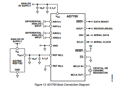
This is a very good data sheet with lots of graphs and data - that might not make immediate sense to you but the first thing to look for is a typical application / basic connection diagram. Later you will find asking more question that the graphs and tables will provide you with answers.

enter image description here

You can clearly see they use a CRYSTAL OR CERAMIC RESONATOR as a clock input.

Connection a crystal directly is permitted for testing only. In production you really need to balance the crystal with matching capacitors so that the freqauicnies do not stray- which chould lead to data corruption or communication problems when the environment changes (temperatue, humidity and pressure) Because testing is short term you will not if hardly see any variation in frequencies from a crystal.

So which crystal should you use? Well- Only the data sheet can provide that answer. It all depends what you want to do. Faster does not mean better.

1
  • 2
    Thanks so much for the insightful answer. I've ordered a handful of 4mhz ceramic resonators to provide a stable clock source. It appears they're less sensitive to environmental variations and include the necessary capacitance. It seems the SPI clocks are driven separately on this, so I can dictate the signaling rates on the RPi.
    – patking
    Commented Mar 20, 2013 at 4:02

Your Answer

By clicking “Post Your Answer”, you agree to our terms of service and acknowledge you have read our privacy policy.

Not the answer you're looking for? Browse other questions tagged or ask your own question.