0

I want to learn how to send ASCII code from Raspberry Pi 3 to a serial device. Communication protocol of Serial device via RS232 (TX, RX pins). I was trying to connect from kermit as follows but I failed;

set line /dev/ttyS0
set carrier-watch off
set speed 9600
set flow none
set parity none set stop-bits 1
connect
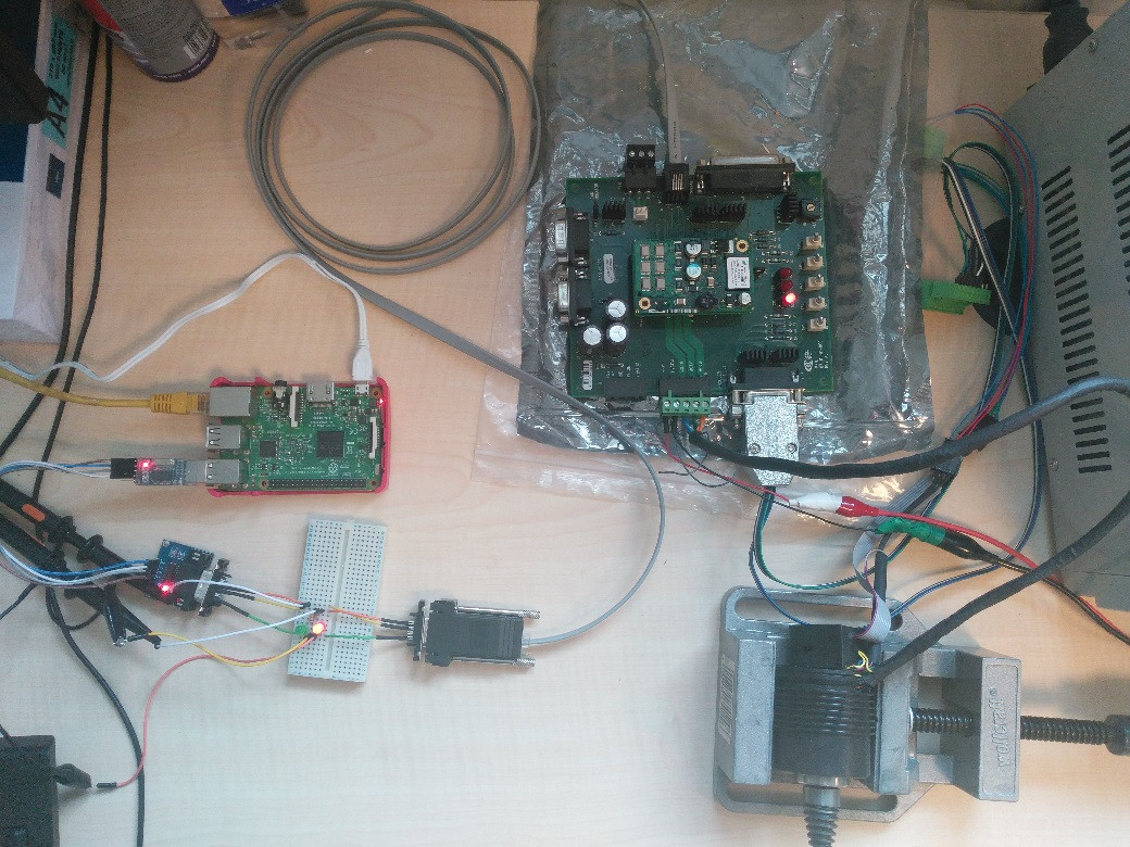
The circuit with RS232-TTL Converter enter image description here

The circuit with USB-TTL Profilic converter enter image description here

3
  • 2
    The Pi is not compatible with a RS232 device which uses voltages in the region of + and - 12V. The Pi's UART is 3V3 TTL (it signals with 0V and 3V3).
    – joan
    Commented Jun 19, 2017 at 15:06
  • Raspberry Pis don't generally have a /dev/ttyS0 device. The GPIO serial port is typically /dev/ttyAMA0
    – scruss
    Commented Jun 19, 2017 at 15:42
  • 1
    Actually ı am using RX-TX pins of Raspberry Pi 3 and RS232-TTL Converter for voltage level shifter. I am not sure these pins are called as RS232. When I googled the issue on the intternet I saw much more information about that Raspberry Pi 3 uses /dev/ttyS0 because of bluetooth and older versions /dev/ttyAMA0. I am confused and I tried both of them in the code but I failed. Commented Jun 20, 2017 at 6:42

3 Answers 3

0

I think this is possible with a Max232 chip or you can use a USB to Serial adapter.

http://elinux.org/RPi_VerifiedPeripherals#USB_UART_and_USB_to_Serial_.28RS-232.29_adapters

A USB to Serial (RS-232) adapter is used the other way around, ie. the USB end connects to the Raspberry Pi and the RS-232 end (DSUB-9 or DSUB-25 pin) to the other device which may be another computer, (old) modem or printer, or some electronic test equipment.

2
  • I have USB to serial adapter of Profilic. I tried this 2 weeks ago but It did not work. Can you help me about coding and how I can check whether there is a connection between RPi 3 and serial device. I will upload the photo of the circuit I am dealing with. By the way, I am stucked about this communication problem for weeks and I want to solve it. Commented Jun 20, 2017 at 6:52
  • This is one of the program to communicate between RPi and serial device; # Serial2.py import serial import time #port = "/dev/ttyAMA0" # Raspberry Pi 2 port = "/dev/ttyUSB0" # Raspberry Pi 3 ser = serial.Serial(port, baudrate = 9600) print ("starting") while True: time.sleep(1) ser.write("r") nbChars = ser.inWaiting() if nbChars > 0: data = ser.read(nbChars) print (data) Commented Jun 20, 2017 at 7:34
0

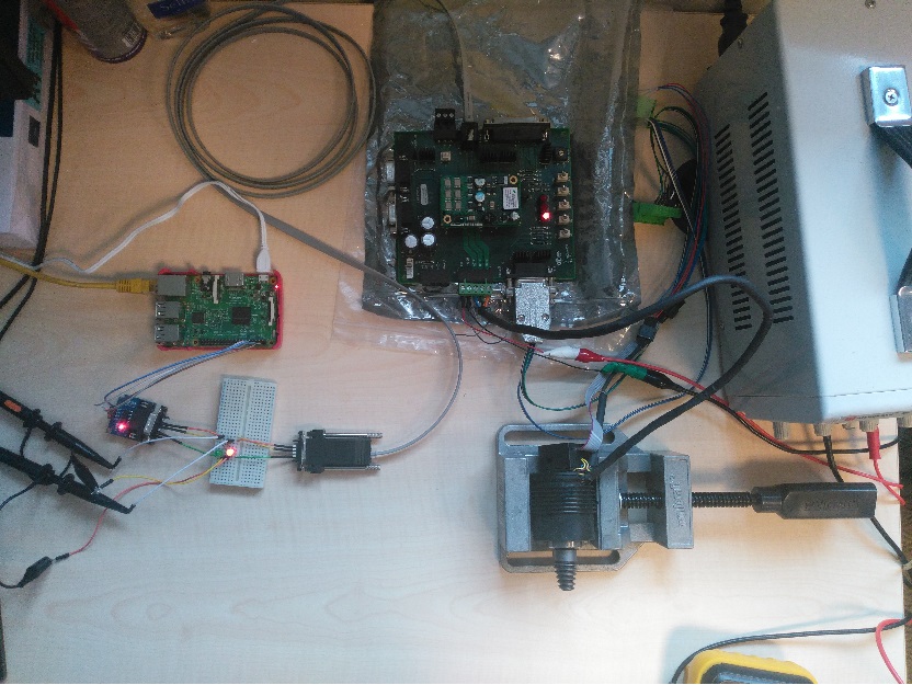
Finally I solved the problem by installing gtkterm on Raspberry Pi. After installing gtkterm I can send ASCII codes to the serial device (motor controller) and rotate the servo motor :)

Now all I need to write a Python program to control the motor. Can anybody help me about how I can write codes of gtkterm on Python?

0

Here is the Python code to control motor by using RPi3 and Copley motor driver. After installing gtkterm on Raspberry Pi 3 this code runs on Python 3 and the motor rotates 100000 counts incrementally for each running.

#This program is written by Mustafa Güler who is Electrical and Electronics Engineer
#at Teknolus Enerji located in METU Technopolis MET Campus.
#The main goal of this program is to make communication between RPi 3 Model B and
#Copley Motor Driver via serial communication protocol


import serial
import time

#Defining the port parameters
port = serial.Serial("/dev/ttyUSB0", baudrate=9600, timeout=3.0)

#Defining the Copley parameters

#Variables____________________bytearrays____________________________________________Copley Parameters
get_actual_motor_position   = [103, 32, 114, 48, 120, 51, 50, 13]                   # g r0x32
absolute_move               = [115, 32, 114, 48, 120, 99, 56, 32, 49, 13]           # s r0xc8 1
set_position                = [115,32,114,48,120,99,97,32,49,48,48,48,48,48,13]     # s r0xca [desired position; i.e. 100000]
abort_move                  = [116, 32, 48, 13]                                     # t 0
initiate_move               = [116, 32, 49, 13]                                     # t 1
initiate_homing             = [116, 32, 50, 13]                                     # t 2
amplifier_reset             = [114, 13]                                             # r
disable_amplifier           = [115, 32, 114, 48, 120, 50, 52, 32, 48, 13]           # s r0x24 0
get_bus_voltage             = [103, 32, 114, 48, 120, 49, 101, 13]                  # g r0x1e
get_amplifier_temperature   = [103, 32, 114, 48, 120, 50, 48, 13]                   # g r0x20
get_serial_baud_rate        = [103, 32, 114, 48, 120, 57, 48, 13]                   # g r0x90
set_function_gen_to_sine    = [115, 32, 114, 48, 120, 57, 56, 32, 50, 13]           # s r0x98 2
set_freq_for_function_gen_Hz= [115, 32, 114, 48, 120, 57, 57, 32, 49, 13]           # s r0x99 1
set_current_amplitude       = [115, 32, 114, 48, 120, 57, 97, 32, 49, 48, 48, 13]   # s r0x9a [current value; 100 for x0.01A]

while True:
    #Read the port information
    read_port = port.readline()

    #"s r0xca 100000" set position
    port.write(bytearray(set_position))
    print('set_position>>>', read_port)
    time.sleep(1)

    #"t 1" initiate move
    port.write(bytearray(initiate_move))
    time.sleep(2)
    print('initiate move>>>', read_port)

    #"g r0x32" get actual motor position
    port.write(bytearray(get_actual_motor_position))

    print('actual motor position>>', read_port)
    time.sleep(1)


port.close()
Your Answer

By clicking “Post Your Answer”, you agree to our terms of service and acknowledge you have read our privacy policy.

Not the answer you're looking for? Browse other questions tagged or ask your own question.