0

I've just started working through the Freenove ultimate starter kit for the Pi Pico, and I'm having trouble understanding why it has so many resistors in this circuit.

I'm following the tutorial document at https://github.com/Freenove/Freenove_Ultimate_Starter_Kit_for_Raspberry_Pi_Pico/blob/master/Python/Python_Tutorial.pdf and have made it to project 2.1. The relevant circuit diagram is attached. Circuit diagram
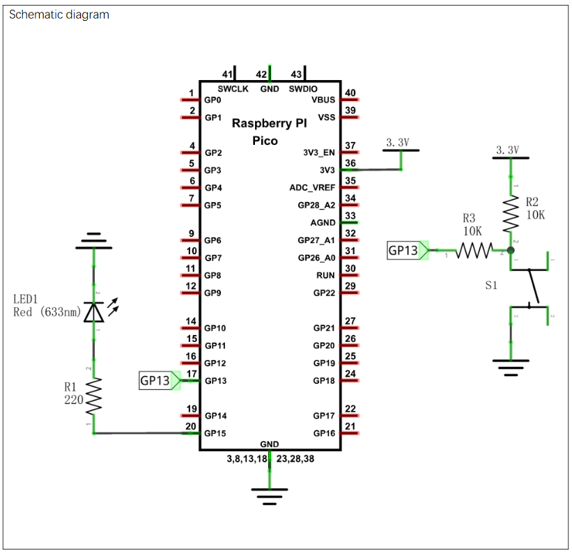
I understand it uses a 220ohm resistor to prevent the LED burning out.

It also uses 2 10k resistors connected to the button - these are the ones that I don't understand. I'm trying to clarify a number of things:

  • Am I correct in thinking that 2 10k resistors in series are the equivalent of a single 20k resistor?
  • Is this done so that we're not passing too much current to the GP13 pin?

I'm having trouble finding an answer as to what the acceptable inputs for the GPIO pins are - the closest I've found is What are the min/max voltage/current values the gpio pins can handle? which recommends no more than 0.5mA. But that's an old post, and not specifically about the Pico.

  • Assuming the GPIO pin could take the full 3.3V @ whatever Amps, would I need either of these resistors?
  • Could I remove safely remove just R2?

This is my first introduction to electronics, so I'm very much in the camp of not even knowing what topics I need to understand. Any advice would be greatly appreciated.

5
  • You picked a rather poor example. "Is this done so that we're not passing too much current to the GP13 pin?" No CMOS; is very high impedance so no current will flow into an INPUT - it is there in case it is configured as OUTPUT (unnecessary IMO). "Could I remove safely remove just R2" No you NEED a pullup (although IMO 10k is too high)
    – Milliways
    Commented Jul 28, 2023 at 10:16
  • Unfortunately anyone can post a "tutorial" on the internet. WHY anyone follows them (and how they find them) is a mystery. Raspberry Pi Ltd. has plenty of good documentation.
    – Milliways
    Commented Jul 28, 2023 at 10:22
  • 3
    3 is "so many" ... OK Commented Jul 28, 2023 at 12:06
  • the resistors have labels ... please use them when referring to the resistors ... R2 and R3 are not in series per se ... you cannot replace them with one resistor and retain the circuit topology
    – jsotola
    Commented Jul 29, 2023 at 0:17
  • @Milliways I bought amazon.co.uk/dp/B09H2TFRN2 which is a pretty cool little kit, with a bunch of stuff nice and cheap. As you've found though, the included tutorials aren't great.
    – AngelsJinx
    Commented Jul 29, 2023 at 12:49

1 Answer 1

2

R2 is a pullup resistor, so the top of S1 is pulled up to 3.3V when open, pulled down to 0V when S1 is closed. R3 limits the maximum current that can be fed into GP13; this is to guard against the pin being set as an output, and the button being pressed, in which case the output would be short-circuited to ground. The 10K value limits the current to well under 1mA, so the output won't be damaged.

When set as an input, GP13 consumes negligible current, so there won't be any voltage drop across R3, and GP13 will receive the full switch voltage.

You are along the right lines in saying that R1 prevents LED1 being burned out, but the important question is: why is it necessary? The answer is that an LED is a constant-voltage device (around 1.8V for a red LED), and it doesn't work with voltages higher or lower than that - higher and too much current will flow, lower and it won't light up. So the series resistor allows the LED to work at a voltage it is comfortable with, and the current (= brightness) is set by the resistor value using ohm's law, I = V / R = (3.3 - 1.8) / 220 = 6.8 mA, which will be a reasonable brightness without overloading the processor output pin.

As others have suggested, this isn't necessarily the best example of the circuit designer's art...

2
  • So R3 is just a guard against misconfiguring GP13? If I were to make the dodgy assumption the code will always be perfect, it could be safely removed? What about R2? GPIO Pins can be configured to pull-up or pull-down internally. If I set it to Pull-up could I remove R2?
    – AngelsJinx
    Commented Jul 29, 2023 at 12:54
  • If you enable an internal pullup, and GP13 is always an input, you can get rid of R2 and R3, and connect the switch directly to GP13. However, internal pullups are quite weak (around 50K) so if the switch is on a long cable, you may get false readings from electrical interference. Also if the switch is physically large, it may not conduct small currents very well, so the pullup will be needed to provide a minimum 'wetting' current.
    – jayben
    Commented Jul 29, 2023 at 13:20

Your Answer

By clicking “Post Your Answer”, you agree to our terms of service and acknowledge you have read our privacy policy.

Not the answer you're looking for? Browse other questions tagged or ask your own question.