2

I have a raspberry pi 2 and trying to build a simple led circuit where a light turns on (so one of the most basic circuits).

I am following this tutorial: https://projects.drogon.net/raspberry-pi/gpio-examples/tux-crossing/gpio-examples-1-a-single-led/

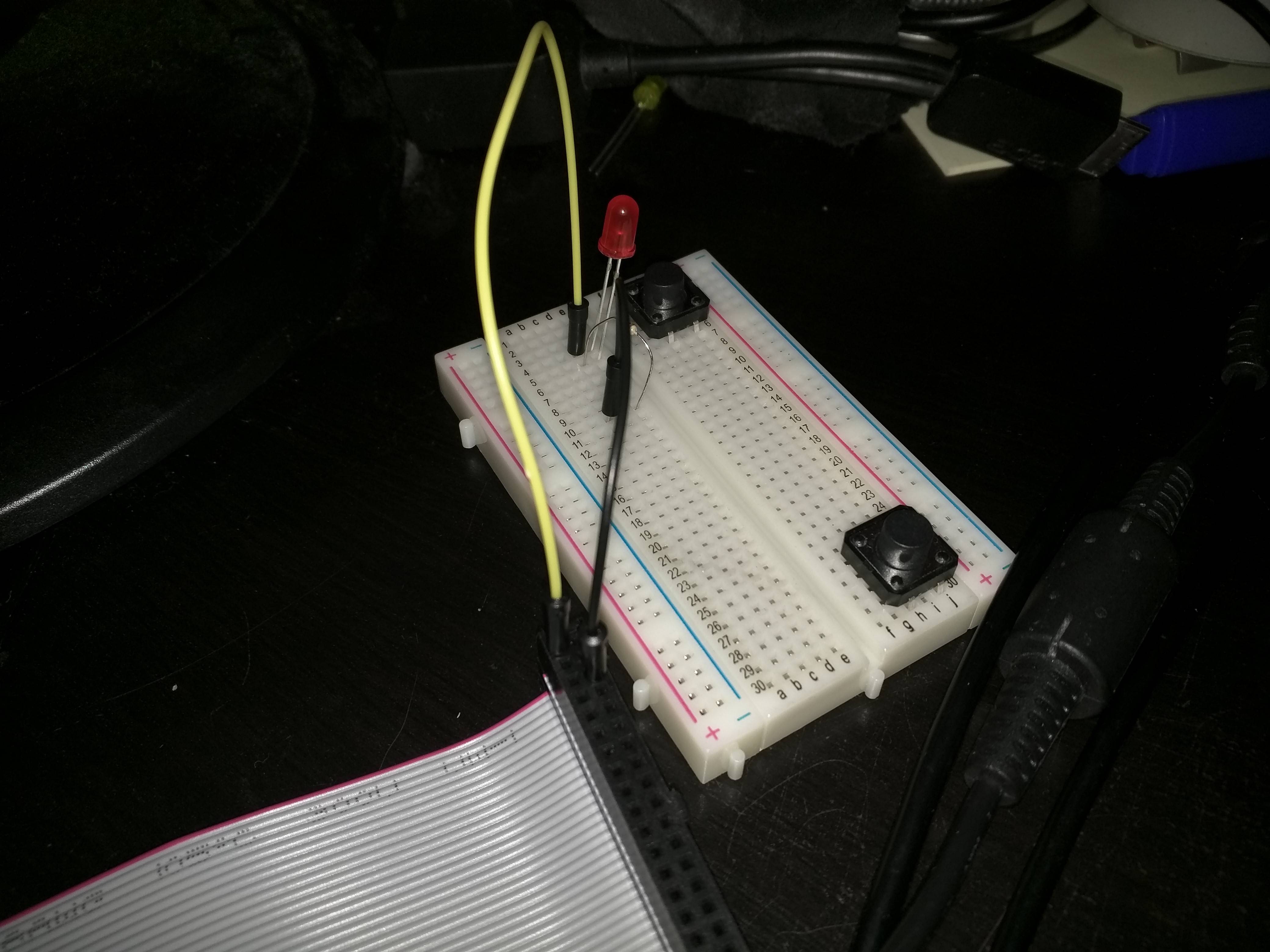
When I connect the bulb using the power supply (i.e. pin 1), then the bulb works fine like so (note blub is very dim so can't really tell in image): LED working

But when I connect to a GPIO (I tried GPIO.0 and GPIO.2) and try to turn it on using:

gpio mode 0 out
gpio write 0 1

Then it dosen't work!

Is it a problem with my raspberry or did I do something wrong?

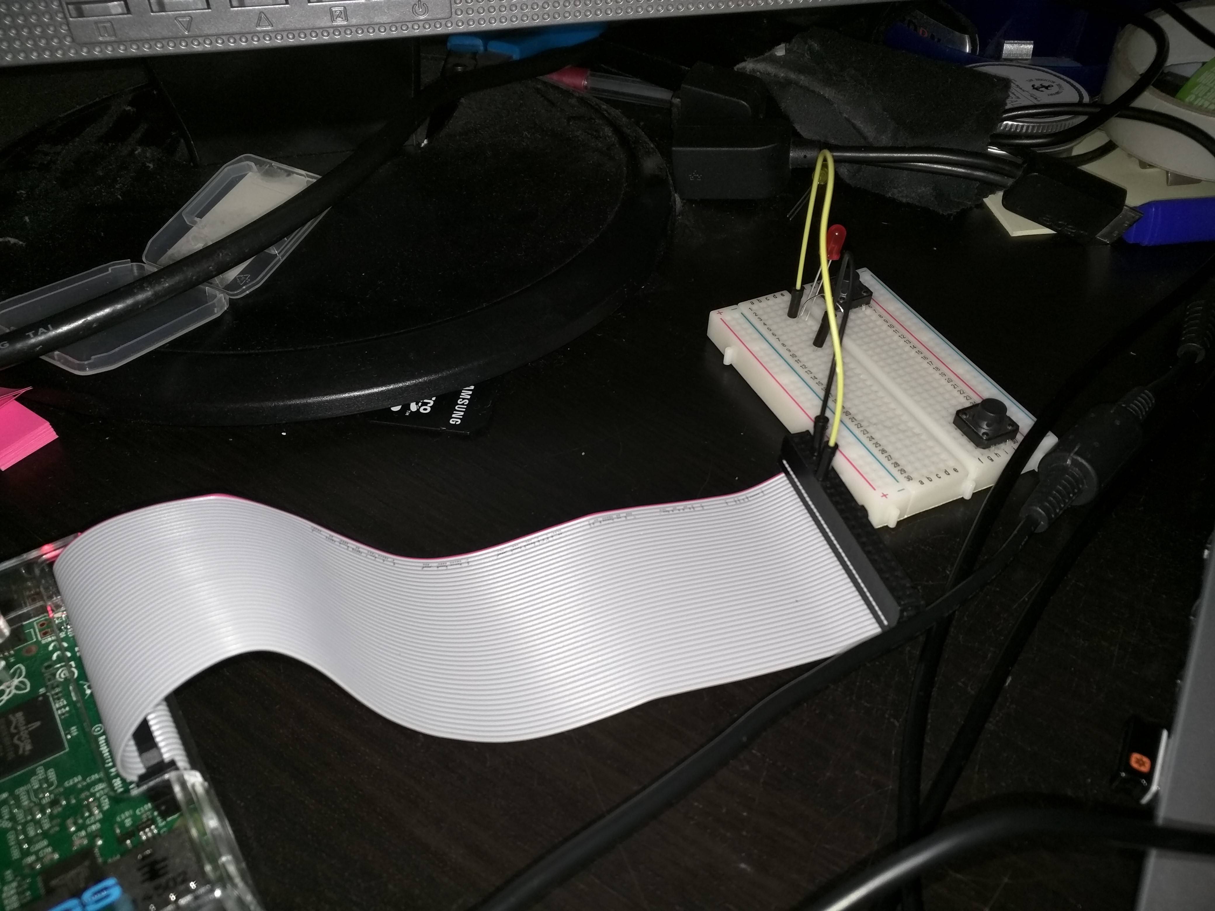
NOTE: I am using male to male jump wires and using a ribbon cable instead of male to female.

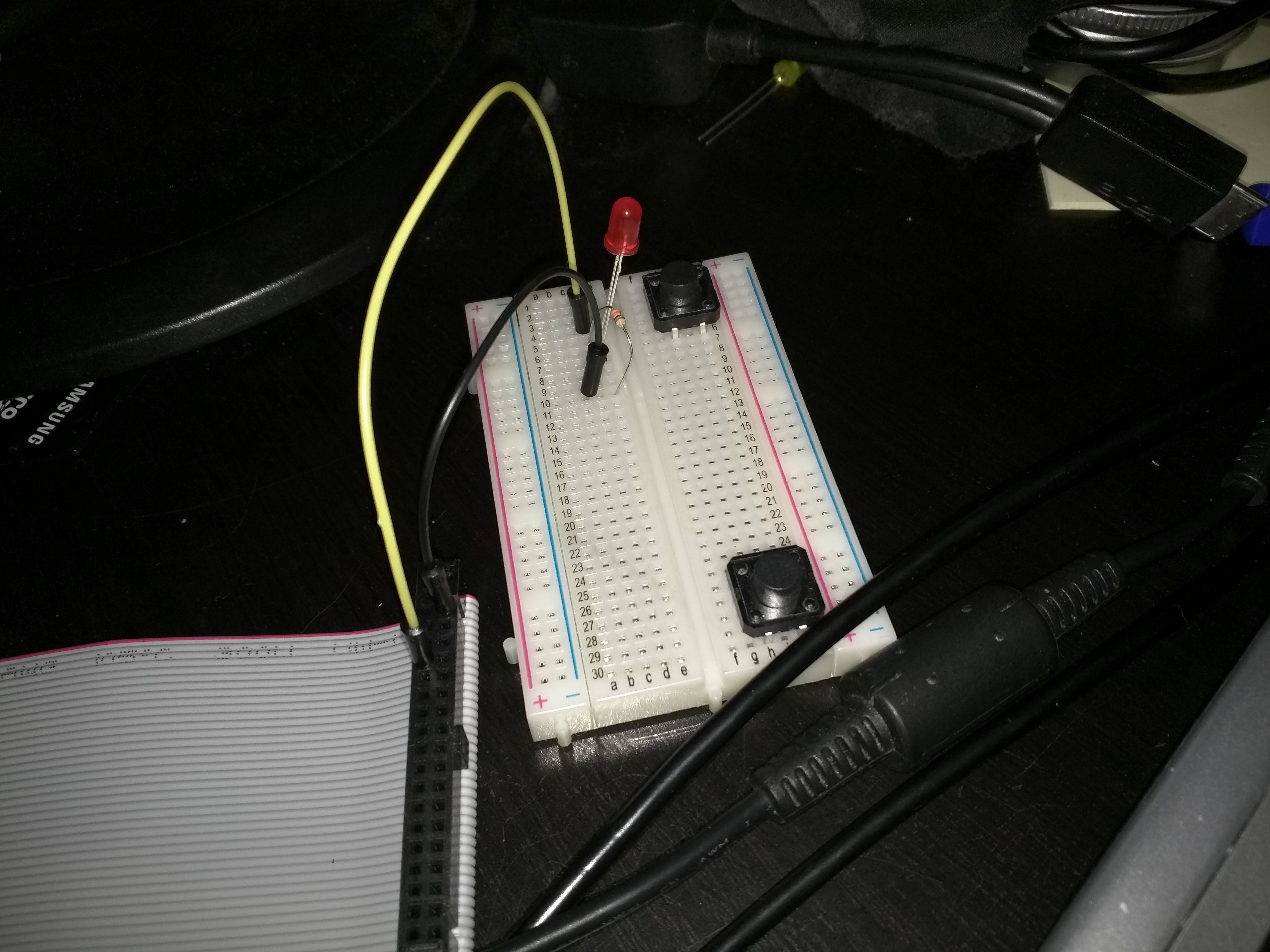
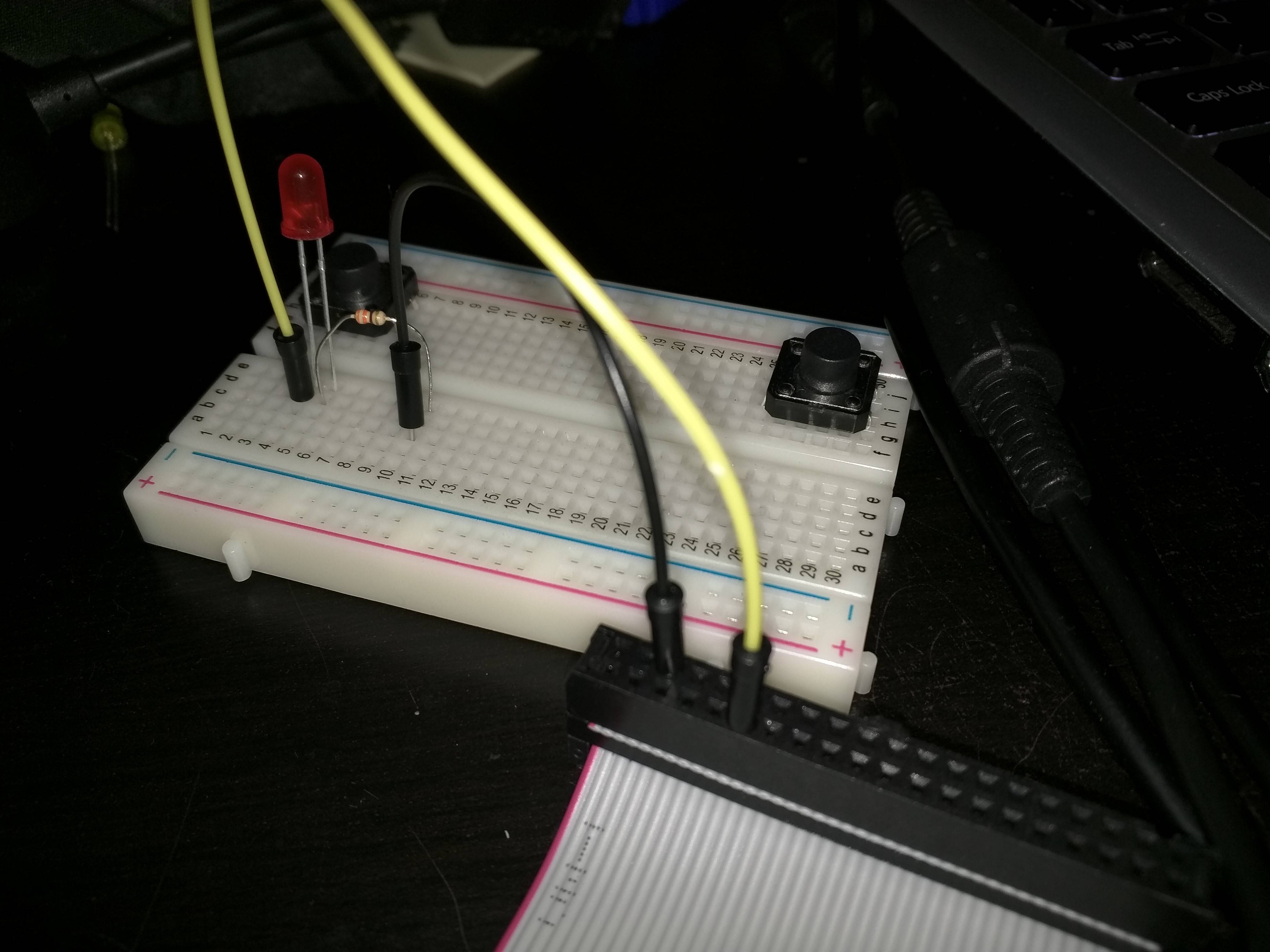
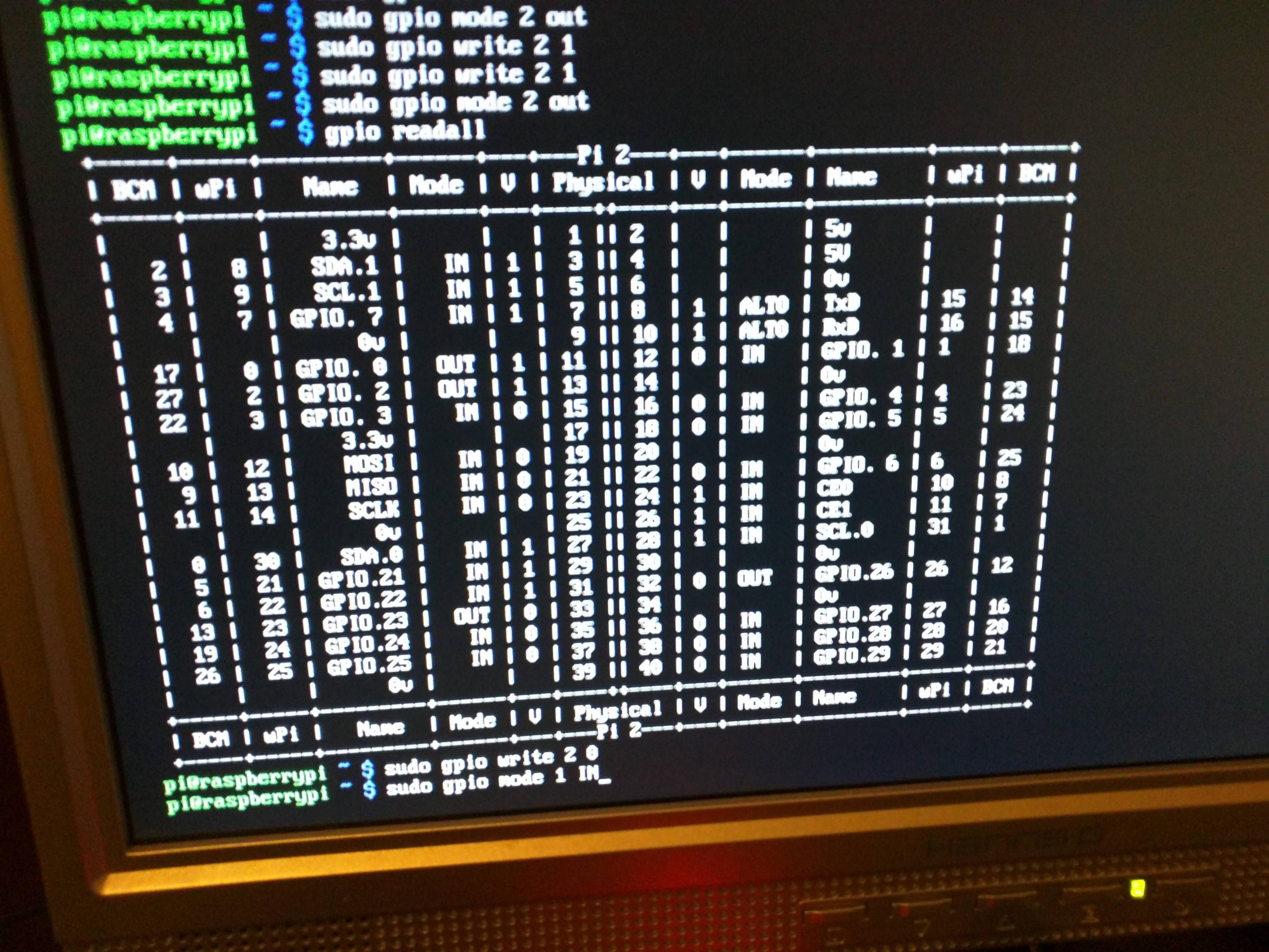
Not working - 1 Not working - 2 Not working -3 gpio readall

7
  • I presume you have a wire going from a GPIO to the LED. If you leave the LED end of the wire but carefully touch the GPIO end of the wire to the 3V3 pin does the LED light? If so the GPIO you are using is not the GPIO you are telling the software to use.
    – joan
    Commented Sep 28, 2015 at 19:04
  • Like I said in the question and shown on the first image, I have already put the wire on the 3.3V pin (i.e. pin 1) and it worked fine. If am not using the right GPIO, then what am I doing wrong. I believe I put it on the right pin and specified the right GPIO as shown on the last 3 diagrams. I can't see anything wrong with it. I also tried different GPIOs Commented Sep 28, 2015 at 20:12
  • 3
    You are using a ribbon cable. That might have swapped the columns. i.e. on the Pi pins 1, 3, 5, etc. (odd numbered pins) are on the left. On the ribbon cable the odd numbered pins may be on the right.
    – joan
    Commented Sep 28, 2015 at 20:15
  • Don't think that's the issue either as like I said, it works when connected to the 3.3V pin. If the columns swapped, then the ground pin would be connected to BCM 3 (SCL) [whatever that is], so would probably not worked! Nice try though :-) Commented Sep 28, 2015 at 20:19
  • You seem to be using pin 11. You are not telling the software to use pin 11.
    – joan
    Commented Sep 28, 2015 at 20:38

2 Answers 2

3

The commonest problems are a mismatch between the GPIOs being physically used and the GPIOs the software is told to use.

There are at least three different numbering schemes in use.

  1. Broadcom GPIO number: the GPIO is identified by specifying its Broadcom number. The end user needs to check where (if at all) the GPIO is connected to the expansion header.
  2. Pin number: The GPIO is identified by the expansion header pin number. Note, that not all pins are connected to GPIOs. Some are connected to the ground, 3V3, and 5V power rails.
  3. wiringPi number: The GPIO number is identified by a "logical" numbering scheme which is neither of the above.

Different software libraries support one or more of the above schemes. You need to check then double check if your circuit does not work as expected.

Additional problems are introduced by cobblers and ribbon cables.

A ribbon cable connected to a cobbler may be inserted the wrong way around at the Pi end or the cobbler end. If you have a meter check that the breadboard gives 3V3 and 5V at the expected points.

If you use a ribbon cable by itself then the columns may have been swapped. i.e. on the Pi pins 1, 3, 5, etc. (odd numbered pins) are on the left. On the ribbon cable the odd numbered pins may be on the right. If you have a meter check that the cable gives 3V3 and 5V at the expected points.


As Phil B. points out take some care when choosing a ribbon cable. An old style 40 pin 40 wire IDE cable will be fine, however the later style 40 pin 80 wire IDE cables will damage the Pi. The 80 wire IDE cables have internal connections which will connect Pi pins which should not be connected.
1
  • 2
    Might be worthwhile to add that one also needs to be careful with the type of Ribbon cable. A dedicated rPi ribbon cable (typically rainbow colored) will work regardless, a 40-wire PC-ribbon cable will work too, but not an 80-wire PC ribbon cable (which also has 40 "holes" in the header).
    – Phil B.
    Commented Sep 29, 2015 at 12:44
1

Did you try checking the polarity of the LED ? Polarity of LED if the polarity is reversed, the LED will NOT light

Also, try with the different GPIO pins (ref diagram: GPIO PIN diagram )

GPIO pins are different from the actual numbering counted from the top/left/right

1
  • Well it worked for the power pin so I don't think polarity is an issue. I am also aware that GIPO pins are different to actual numberings as shown by my images. I have also tried different GIPO pins. Commented Sep 28, 2015 at 20:03

Your Answer

By clicking “Post Your Answer”, you agree to our terms of service and acknowledge you have read our privacy policy.

Not the answer you're looking for? Browse other questions tagged or ask your own question.