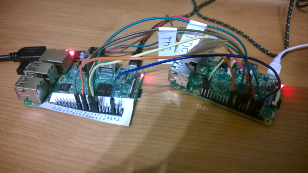
I am trying to debug a Raspberry Pi 3B (rev 1.2) bare metal application using JTAG. I have no JTAG adapter so I am using another Raspberry Pi (3B rev 1.2) as JTAG adapter. I am using OpenOCD and it looks like it's working. I can access all cores but it randomly reports DAP errors.
Connections are simple wires.
For example when I run
openocd -f rpi_swd.cfg -c "bindto 0.0.0.0" -f rpi_target.cfg
it prints
    Open On-Chip Debugger 0.10.0+dev-00920-g6ea43726 (2019-07-06-16:29)
Licensed under GNU GPL v2
For bug reports, read
    http://openocd.org/doc/doxygen/bugs.html
trst_and_srst separate srst_gates_jtag trst_push_pull srst_push_pull connect_deassert_srst

Info : Listening on port 6666 for tcl connections
Info : Listening on port 4444 for telnet connections
Info : BCM2835 GPIO JTAG/SWD bitbang driver
Info : JTAG and SWD modes enabled
Info : clock speed 1001 kHz
Info : JTAG tap: rpi3.tap tap/device found: 0x4ba00477 (mfg: 0x23b (ARM Ltd.), part: 0xba00, ver: 0x4)
Info : rpi3.a53.0: hardware has 6 breakpoints, 4 watchpoints
Info : rpi3.a53.1: hardware has 6 breakpoints, 4 watchpoints
Error: JTAG-DP STICKY ERROR
Error: JTAG-DP STICKY ERROR
Error: JTAG-DP STICKY ERROR
Error: JTAG-DP STICKY ERROR
Error: JTAG-DP STICKY ERROR
Error: JTAG-DP STICKY ERROR
Error: JTAG-DP STICKY ERROR
Error: JTAG-DP STICKY ERROR
Error: JTAG-DP STICKY ERROR
Error: JTAG-DP STICKY ERROR
Info : rpi3.a53.2: hardware has 6 breakpoints, 4 watchpoints
Error: JTAG-DP STICKY ERROR
Error: JTAG-DP STICKY ERROR
Error: JTAG-DP STICKY ERROR
Error: JTAG-DP STICKY ERROR
Error: JTAG-DP STICKY ERROR
Error: JTAG-DP STICKY ERROR
Error: JTAG-DP STICKY ERROR
Error: JTAG-DP STICKY ERROR
Error: JTAG-DP STICKY ERROR
Error: JTAG-DP STICKY ERROR
Info : rpi3.a53.3: hardware has 6 breakpoints, 4 watchpoints
Error: Invalid ACK (6) in DAP response
Error: JTAG-DP STICKY ERROR
Error: JTAG-DP STICKY ERROR
Error: JTAG-DP STICKY ERROR
Error: JTAG-DP STICKY ERROR
Error: JTAG-DP STICKY ERROR
Error: JTAG-DP STICKY ERROR
Error: JTAG-DP STICKY ERROR
Error: JTAG-DP STICKY ERROR
Error: JTAG-DP STICKY ERROR
Error: JTAG-DP STICKY ERROR
Info : rpi3.a53.0 cluster 0 core 0 multi core
Info : Listening on port 3333 for gdb connections
Info : Listening on port 3334 for gdb connections
Info : Listening on port 3335 for gdb connections
Info : Listening on port 3336 for gdb connections
It looks that it is working. I have tried that I can succesffully halt each core, place breakpoints continues execution and view variables content. But it randomly prints DAP errror and some JTAG-DP STICKY ERROR and sometimes debuging crash.
File rpi_swd.cfg has modified pin numbers and allowed jtag and the content is:
#
# Config for using Raspberry Pi's expansion header
#
# This is best used with a fast enough buffer but also
# is suitable for direct connection if the target voltage
# matches RPi's 3.3V and the cable is short enough.
#
# Do not forget the GND connection, pin 6 of the expansion header.
#

interface bcm2835gpio

bcm2835gpio_peripheral_base 0x3F000000

# Transition delay calculation: SPEED_COEFF/khz - SPEED_OFFSET
# These depend on system clock, calibrated for stock 700MHz
# bcm2835gpio_speed SPEED_COEFF SPEED_OFFSET
bcm2835gpio_speed_coeffs 146203 36

# Each of the JTAG lines need a gpio number set: tck tms tdi tdo
# Header pin numbers: 23 22 19 21
bcm2835gpio_jtag_nums 25 24 23 22
# or if you have both connected,
# reset_config trst_and_srst srst_push_pull

# Each of the SWD lines need a gpio number set: swclk swdio
# Header pin numbers: 22 18
bcm2835gpio_swd_nums 25 24

# If you define trst or srst, use appropriate reset_config
# Header pin numbers: TRST - 26, SRST - 12

bcm2835gpio_trst_num 7
#reset_config trst_only

bcm2835gpio_srst_num 18
#reset_config srst_only srst_push_pull

# or if you have both connected,
reset_config trst_and_srst srst_push_pull
and file rpi_target.cfg contains
transport select jtag

# we need to enable srst even though we don't connect it
reset_config trst_and_srst

adapter_khz 1000
jtag_ntrst_delay 500

if { [info exists CHIPNAME] } {
  set _CHIPNAME $CHIPNAME
} else {
  set _CHIPNAME rpi3
}

#
# Main DAP
#
if { [info exists DAP_TAPID] } {
   set _DAP_TAPID $DAP_TAPID
} else {
   set _DAP_TAPID 0x4ba00477
}

jtag newtap $_CHIPNAME tap -irlen 4 -ircapture 0x1 -irmask 0xf -expected-id $_DAP_TAPID -enable
dap create $_CHIPNAME.dap -chain-position $_CHIPNAME.tap

set _TARGETNAME $_CHIPNAME.a53
set _CTINAME $_CHIPNAME.cti

set DBGBASE {0x80010000 0x80012000 0x80014000 0x80016000}
set CTIBASE {0x80018000 0x80019000 0x8001a000 0x8001b000}
set _cores 4

for { set _core 0 } { $_core < $_cores } { incr _core } {

    cti create $_CTINAME.$_core -dap $_CHIPNAME.dap -ap-num 0 \
        -ctibase [lindex $CTIBASE $_core]

    target create $_TARGETNAME.$_core aarch64 \
        -dap $_CHIPNAME.dap -coreid $_core \
        -dbgbase [lindex $DBGBASE $_core] -cti $_CTINAME.$_core

    $_TARGETNAME.$_core configure -event reset-assert-post "aarch64 dbginit"
    $_TARGETNAME.$_core configure -event gdb-attach { halt }
}
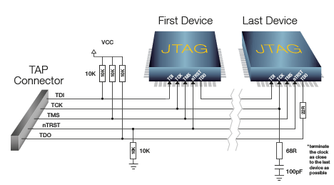
How to fix it? What am I doing wrong? Do I need to add some resistor or capacitor on data wires?


