1

first off, I'm a noob when it comes to hardware/electronics. Barely started and not planning on getting too deep in it.

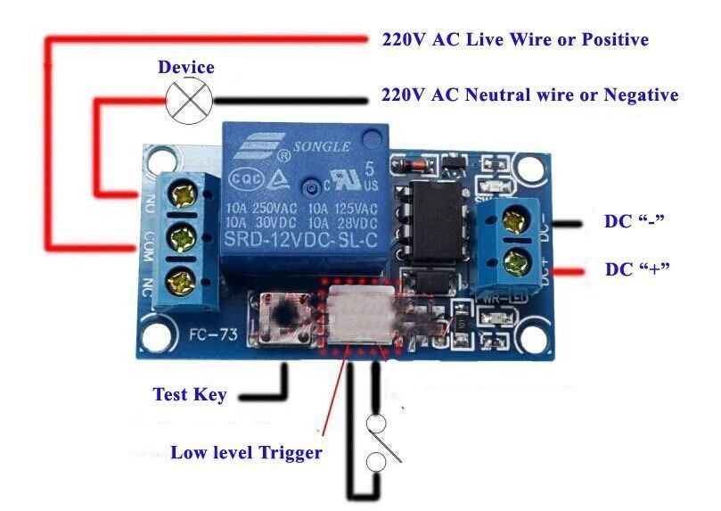
Now, what I am trying to do may not be possible, hence this question. I have this latching relay latching relay and it works as expected (not sure if it counts, but I have the 5V version of this, no the pictured 12V. Everything else seems the same though)

There are 2 pins in that white area that is the "low level trigger". I found that I can take just 1 of the pins from the "low level trigger" and if I tap it to the DC "-" connector, it will latch (basically, acts like the button). It's the one from the left; it will not work with the one from the right.

Now I'm trying to find a way to connect everything so that the relay is powered by it's own 5V power source, the RPI is powered by it's own power source, and I want to connect just 1 pin from the RPI to control the latching on the relay (so one of those 2 pins/wires on the relay).

Is there any way I can achieve this?

Thanks.

1
  • you will need two wires connected to the RPi ..... one is the control signal voltage and the other is the reference voltage (usually ground)
    – jsotola
    Commented May 2, 2019 at 22:43

2 Answers 2

1

Question

  1. I have a 5V latch relay, and I have tested it manually, by hand and found everything OK.

  2. How to use one Rpi GPIO pin to do automatic (say python software) control?

Answer

No problem. Let us first begin with the latch relay features/operation/functional user guide/specification as display below.
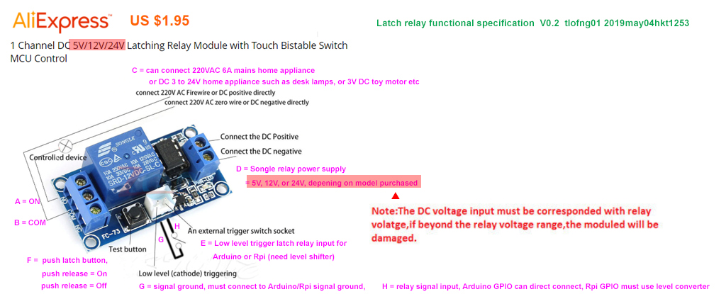
latch relay spec

Now I have drawn a schematic showing 4 parts/modules. Each of the 4 parts are loosely coupled, and can be separately tested. The OP has already manually by hand tested one of the four parts - the latch relay.

The rightmost part can be easily tested using a 24VDC desk lamp.

The Rpi part can also be easily tested by a simple python blinky LED program.

The 3V3 to 5V0 logical level converter/up shifter can be a simple 2N2222 pull down/sink driver, or any other circuits with a similar converter function.

As the OP has more than one relay, I would recommend the HCT125 quad logical level converter, as described in the reference below. There are many more ways to do level shifting. The second link describes some of them.

74AHCT125 - Quad Logical Level-Shifter - Adafruit

Four ways to do logical level shifting - tlfong01

After all 4 parts/modules are separately tested, the OP can do incrementally integration and testing. For example, add logical level converter to Rpi, and test two together. Then add latch relay to the two, and tested three together.

There is no need to add the desk lamp when testing the left three modules, because relays switches with a click sound, implying Songle switch contacts are breaking or making. Finally the desk lamp can be added, and all 4 modules tested together, and day is done!
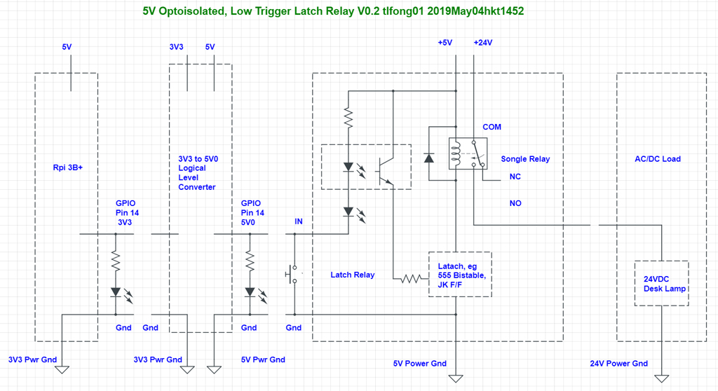
latch relay test

Get around of replacing logical level converter by just a 4k7 resistor

Actually there is quick and dirty get around of not using any logical level converter. This get around or trick is to insert a 4k7 resistor between Rpi GPIO pin and latch relay input pin, between points A and B as shown in the picture below.

For testing only the pink part (desk lamp) can be removed.

However, Rpi 3V3 ground and Latch relay 5V power ground still needed to be connected, to make a common signal reference point.

Warning - There is a risk of this get around. There is 1% chance that you Rpi will be killed immediately, 2% chance killed in 30 minutes, 3% chance Rpi's life shortened. The killer cause is called "latch up" effect, which happens when Rpi GPIO is connected through a resistor to 5V. The latch up effect is a subtle concept which I am not able to explain in less than 15 minutes, using less than 500 words, without a couple of illustrations. You might like to read more details in the references below.
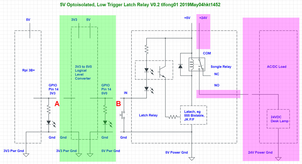
get around

/ to continue, ...

References

How to kill your Rpi instantly, by connecting its 3V3 GPIO pin to a 5V device

How to kill your Rpi slowly, in 30 minutes, by connecting its 3V3 GPIO pin to a 5V device

How to use a 4k7 resistor to get around the "Rpi High not high enough" problem with a device compatible to Arduino but not Rpi

Why do networks need a common ground cable?

Amazon HiLetgo 5V 1 Channel Latching Relay Module with Touch Bistable Switch - US$6

AliExpress Capacitive Touch Latching Self-locking Switch Relay Module
3
  • Thank you for the detailed explanation. Actually all I needed was " However, Rpi 3V3 ground and Latch relay 5V power ground still needed to be connected to make a common signal reference point." That indeed solves my problem. And the logical level converter requirement/problems I did not know about/understand them so thank you for saving my ... pi :) I was going to go for the resitor solution as read on a few places.
    – ciuly
    Commented May 4, 2019 at 21:13
  • You are welcome. Actually the "no common ground" thing often puzzles newbies and ninja alike. Perhaps I can explain it better later. BTW, I have updated my answer with some case studies on latching up. You may like to read them at your leisure. Good luck to your brave experiments! :)
    – tlfong01
    Commented May 5, 2019 at 1:52
  • Interesting things to read, thanks.
    – ciuly
    Commented May 5, 2019 at 15:06
2

Short answer: "Yes, there is a way to achieve this."

That said, your question omits some details that are needed for a complete answer. But we'll start from what we know, or can reasonably assume, and go from there. One caveat: Your Raspberry Pi may be ruined if one of us makes a mistake: either I make a mistake in my instructions, or you make a mistake in executing them. I'll cover some "safeguards", but if your hardware knowledge is very limited, then your risk increases. If you're OK with that, we'll go ahead. If not, go back to software :)

From the information in your question, it seems reasonable to assume that the "low level trigger on the left" may be used for your "one pin connection" to the RPi. However, there is one important caveat:

DO NOT connect the low level trigger on the left directly to the RPi. It likely has 5VDC on it. If it does, and you connect it directly to a GPIO pin, your RPi will become a paperweight. This is because the RPi GPIO pins are biased at 3.3VDC, and they are very fragile.

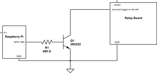
Instead, you will need an "interface" between the low level trigger on the left and the RPi. I'll show this generically in the schematic below. Basically, it will work like this:

Your software program on the RPi will drive the GPIO pin you've chosen to an "active high" state (i.e. its output is 3.3VDC). The GPIO pin will be connected to the "base" terminal of the transistor Q1. Once the GPIO pin goes "high", transistor Q1 will be "turned on", and conduct current between its collector and emitter terminals.

schematic

simulate this circuit – Schematic created using CircuitLab

And so, "this" is a way to achieve your objective. I'll not go further as that may be a waste of time. Review this, and if you'd like to proceed, post a comment. We'll go from there.

9
  • Thanks for your answer. Uhm... I obviously did the "DO NOT" part. I usually only ask questions when I failed in all my attempts and google doesn't help.for whatever reasons. Safeguards, yes, will do whatever you guys suggest to keep my RPI as safe as possible. I accept that accidents happen. Fingers crossed. I think the reason why it's not working, and I hope I'm not being an idiot, is because the "left relay pin" requires a negative signal to latch? While RPI outputs a positive one. Which could also explain why I didn't fry my RPI. I see in schematics that GND's are connected. Is that a must?
    – ciuly
    Commented May 2, 2019 at 14:02
  • reason for the must question is that will get me 2 wires going from RPI to the relay which is what I am trying to avoid. Actual configuration is like 10-15 relay across the house, between 4-15m from the RPI. Just too many wires, and a big spread :)
    – ciuly
    Commented May 2, 2019 at 14:04
  • 1
    Too bad we can't change the laws of physics to suit your needs. I'll speak to Mr. Maxwell next I see him :)
    – Seamus
    Commented May 2, 2019 at 14:13
  • We don't need to go that far. Just think a little out of the box. After all we're talking about the need for a potential difference between 2 ends of the same wire. You are thinking inside the box requiring the 2 points to be in the RPI, I am trying to move one of them out, since both my "ends of the same 1 wire", RPI and relay, have their own potential differences, so can we make that work? I can accept a "no" as long as it comes with reasonable explanation ;) Thanks
    – ciuly
    Commented May 2, 2019 at 14:36
  • @ciuly : I don't mean to be rude, but it doesn't seem to me that you know what you're talking about. "Two ends of the same wire" for connecting two different potentials sounds like some sort of semantic nonsense. Please don't waste our time here with that... some people have actual problems they want help with.
    – Seamus
    Commented May 2, 2019 at 14:45

Your Answer

By clicking “Post Your Answer”, you agree to our terms of service and acknowledge you have read our privacy policy.

Not the answer you're looking for? Browse other questions tagged or ask your own question.